Rotating shaft for automatic gear shifter

A technology for automatic shifting and rotating shafts, applied to components with teeth, transmission control, belts/chains/gears, etc., can solve problems such as troublesome assembly and complex structure, and achieve simple assembly, simple structure, and simple structure Effect

Pending Publication Date: 2019-10-22
NINGBO YONGXIN AUTO COMPONENTS MFG
View PDF0 Cites 1 Cited by
  • Summary
  • Abstract
  • Description
  • Claims
  • Application Information

AI Technical Summary

Problems solved by technology

[0002] The automatic transmission shift mechanism is an important part of the automobile transmission system. Its working principle is to drive the cable through the handle rod to push the rotating shaft, and to drive the rocker arm of the gearbox through the cable to drive the switch between various gears. In the mechanism, there is a rotating shaft at the lower end of the handle rod. According to the existing technology, the rotating shaft adopts a plastic structure and is installed on the handle rod through an undercut assembly method. The structure is complicated and the assembly is troublesome.

Method used


Image

  • Rotating shaft for automatic gear shifter
  • Rotating shaft for automatic gear shifter
  • Rotating shaft for automatic gear shifter

Examples


Embodiment Construction

[0020] The present invention will be further described below in conjunction with the drawings and specific embodiments.

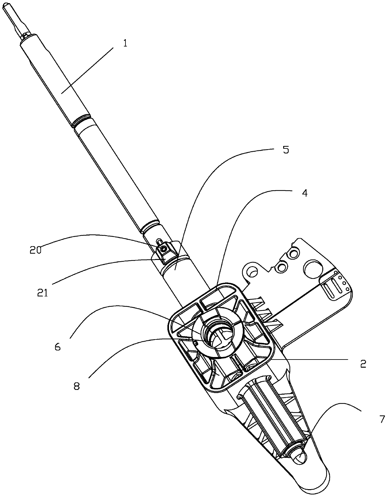
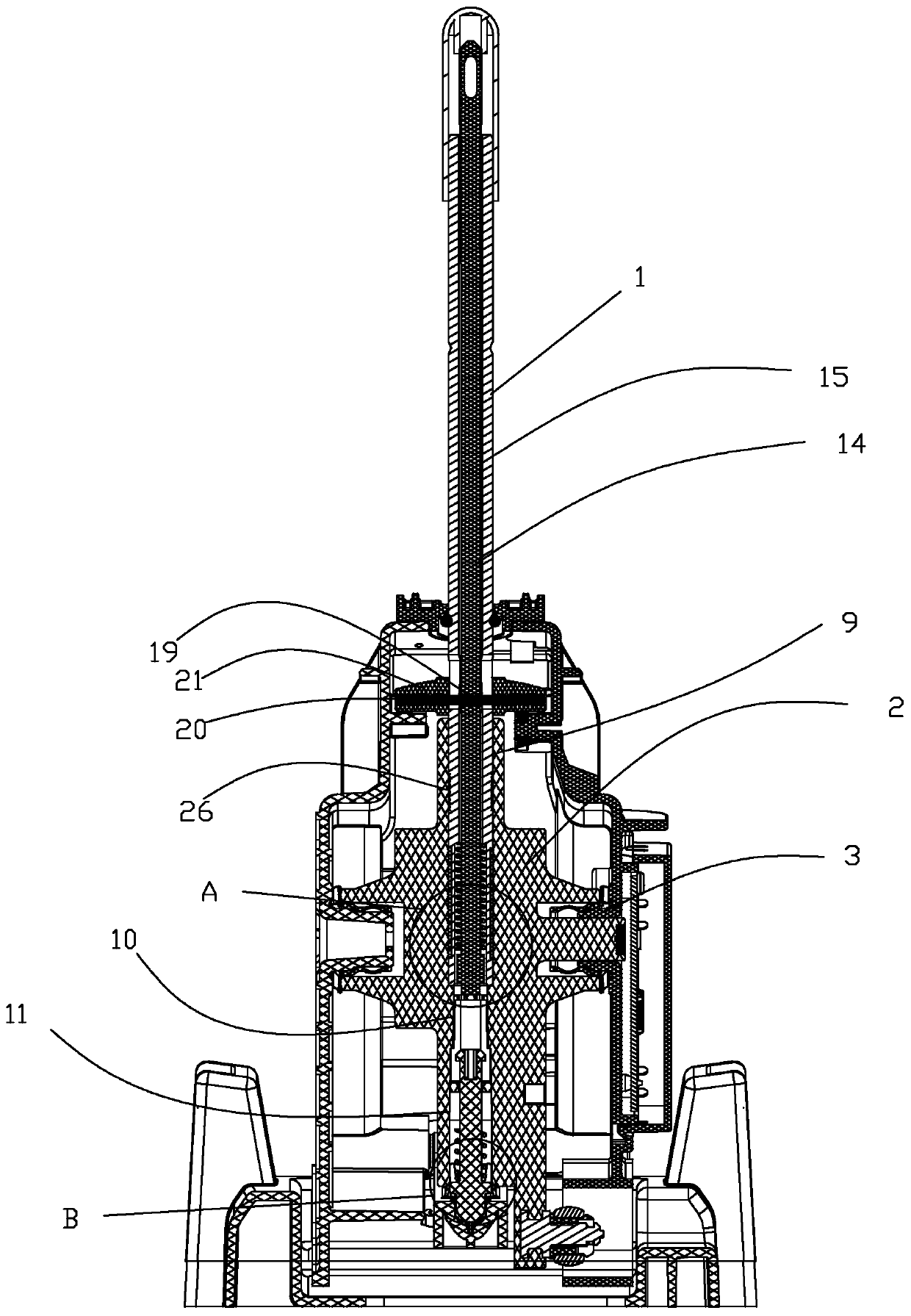
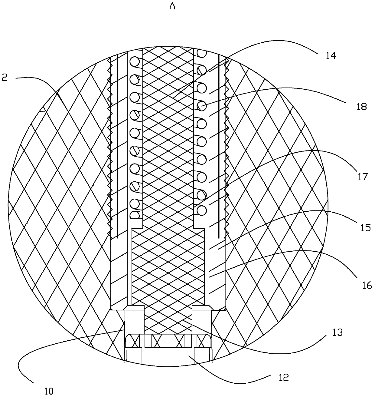
[0021] As shown in the figure, the present invention provides a rotating shaft for an automatic shifter, which includes a handle 1, a rotating shaft 2 and a toggle lever 7 arranged in the automatic shifter, and also includes a shaft sleeve 12 and an automatic gear shifter. The ring seat 3 on the left and right sides of the shifter, the rotating shaft 2 includes a square seat 4 and a vertical pipe 5. The front and rear sides of the square seat 4 are provided with protrusions 6 protruding from the side of the square seat 6. A groove 8 is provided on the protrusion 6, and the ring seat 4 is rotationally matched with the groove 8, the vertical pipe 5 is arranged in the square seat 4, and the vertical pipe 5 extends from the upper and lower sides of the square seat 4, respectively. At both ends, the vertical pipe 5 is provided with a channel along the axis of the v...


PUM


Abstract

The invention discloses a rotating shaft for an automatic gear shifter. The rotating shaft comprises a handle, a rotating shaft body arranged in the automatic gear shifter, a poke rod, a shaft sleeveand annular seats arranged on the left and right sides of the automatic gear shifter; the rotating shaft body comprises a square seat and a vertical tube; bumps protruded out of the side of the squareseat are arranged on the front side and the rear side of the square seat; the bumps are provided with grooves; the annular seats are rotationally matched with the grooves; the vertical tube is arranged in the square seat and extends out of the upper end and the lower end of the square seat; the vertical tube is internally provided with a channel along the axial direction of the vertical tube; thelower end of the handle is in sliding fit with the upper end of the channel; the shaft sleeve is in a sliding fit with the middle end of the channel; the upper end of the poke rod is in sliding fit with the inner part of the shaft sleeve; the lower end of the poke rod is in sliding fit with the lower end of the channel; and the handle can extrude the shaft sleeve. The invention provides the rotating shaft with simple structure and assembly for the automatic gear shifter.

Description

Technical field [0001] The present invention relates to the technical field of automatic shifters, and in particular to a rotating shaft for automatic shifters. Background technique [0002] The automatic gearbox shifting mechanism is an important part of the automobile transmission system. Its working principle is to drive the cable through the handle rod to push the shaft, and to push the gearbox rocker arm through the cable to drive the switch between various gears. A rotating shaft is arranged at the lower end of the handle rod in the mechanism. According to the prior art, the rotating shaft adopts a plastic structure and is mounted on the handle rod through an inverted buckle assembly method. The structure is complicated and the assembly is troublesome. Summary of the invention [0003] The technical problem to be solved by the present invention is to overcome the above-mentioned defects of the prior art and provide a rotating shaft for an automatic shifter with a simple stru...

Claims


Application Information

Patent Timeline
Patent Type & Authority Applications(China)
IPC IPC(8): F16H59/02
CPCF16H59/0278
Inventor 朱梓军郭海宽陈军葛颖颖叶浩梁王威
Owner NINGBO YONGXIN AUTO COMPONENTS MFG
Why Eureka
Try Eureka