Side joint pillar type electric melting pipe fitting

An electrofusion pipe fitting and column type technology, which is applied in the direction of pipes/pipe joints/pipes, pipe connection layout, mechanical equipment, etc., can solve the problems of large overall positioning outer diameter and terminal occupation, etc. small space effect

Active Publication Date: 2019-10-22
优捷特环保科技有限公司
View PDF13 Cites 2 Cited by
  • Summary
  • Abstract
  • Description
  • Claims
  • Application Information

AI Technical Summary

Problems solved by technology

The terminal of the electric fusion pipe fitting is installed on the outer wall of the electric fusion pipe fitting, and the terminal itself occupies a certain size, so that its overall positioning outer diameter is larger

Method used


Image

  • Side joint pillar type electric melting pipe fitting
  • Side joint pillar type electric melting pipe fitting
  • Side joint pillar type electric melting pipe fitting

Examples


Embodiment 1

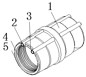
[0061] Such as figure 1 As shown, the present invention discloses a side post-type electrofusion pipe fitting, which includes a pipe body 1 and two terminals 2 arranged on the end wall of the end, and the pipe body includes two ends 3 and a first Heating wire 4; the first hot-melt material layer 5 is fixed on the inner wall surface of the pipe body; and the first heating wire is fixed in the first hot-melt material layer; both ends of the first heating wire are electrically connected respectively terminal. The terminal is arranged on the outer wall of the pipe body. The terminal is partially buried in the pipe body, and its top is exposed outside the pipe body. The terminal centerline is perpendicular to the end wall of the terminal.

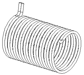
[0062] Its heating wire is as figure 2 As shown, the first heating wire includes two parallel cylindrical spiral heating wires that spiral in the same direction, and the two cylindrical spiral heating wires are connected at the same side of...

Embodiment 2

[0066] Such as Figure 4 As shown, the present invention discloses a side-connected post-type electrofusion pipe fitting, which includes a pipe body and two lugs arranged on the end wall of the end head on the pipe body, and the pipe body includes two end ends and the first heating wire; the first hot-melt material layer is fixed on the inner side of the pipe body; and the first heating wire is fixed in the first hot-melt material layer; the two ends of the first heating wire are respectively electrically connected terminal. The terminal is arranged on the outer wall of the pipe body. The terminals are all installed at the end away from the nozzle. The terminals are all embedded in the pipe body, and the tops thereof are exposed outside the pipe body.

Embodiment 3

[0068] Such as Figure 5 As shown, the present invention discloses a side-connected post-type electrofusion pipe fitting, which includes a pipe body and four lugs respectively arranged on the end walls of the ends on both sides of the pipe body. The pipe body includes two A terminal and the first heating wire; the first hot-melt material layer is fixed on the inner side of the pipe body; and the first heating wire is fixed in the first hot-melt material layer; the two ends of the first heating wire are respectively Electrically connect the lugs. The terminal is arranged on the outer wall of the pipe body. The terminals are all installed at the end away from the nozzle. The terminal is partially buried in the pipe body, and its top is exposed outside the pipe body. An installation groove 6 is provided on the outer edge of the end wall of the terminal head, and the terminal head is installed in the installation groove.


PUM


Abstract

The invention provides a side joint pillar type electric melting pipe fitting which comprises a pipe body, at least two connector lugs, a first hot melting type material layer and a first electric heating wire. The connector lugs are arranged on the end face wall of the end heads. The first hot melting type material layer is at least locally fixed to the inner side wall and / or the outer side surface. The first electric heating wire is fixed in the first hot melting type material layer. The two ends of the first electric heating wire are electrically connected with the connector lugs correspondingly. The connector lugs of the side joint pillar type electric melting pipe fitting are installed on the end face wall of the pipe body, the connector lugs can be inserted in an insertion piece to achieve butt joint positioning and fixing effects, the maximum outer diameter of the electric melting pipe body is smaller (the height of the connector lugs which are arranged in the radial direction does not exist), and the space occupied by the whole electric melting pipe body is reduced.

Description

technical field [0001] The invention relates to the field of electric fusion pipe fittings, in particular to a side column type electric fusion pipe fitting. Background technique [0002] At present, electrofusion pipe fittings refer to pipe fittings that use the high temperature generated by electric current to melt multiple polyethylene pipe fittings that are in contact with each other and connect them together. Compared with traditional pipe fittings, such as threaded connections and plug-in connections, due During the connection process, it is necessary to rotate or apply force to the pipe fittings. For some large pipe fittings, the on-site construction operation is very difficult. The electrofusion connection method has outstanding advantages in construction engineering. For polyethylene pipe fittings, the use of electrofusion welding technology can easily Connect the two fittings. [0003] In recent years, electrofusion pipe fittings have been widely used in the field...

Claims


Application Information

Patent Timeline
Patent Type & Authority Applications(China)
IPC IPC(8): F16L47/03
CPCF16L47/03
Inventor 刘向东聂辉
Owner 优捷特环保科技有限公司
Why Eureka
Try Eureka