
Valve piston arrangement for a vibration damper

一种减振器、活塞的技术,应用在减振器、液体减振器、减震器等方向,能够解决高弯曲应力变形、阻碍电控阀滑动等问题,达到抗弯力矩高、简单制造、简化制造的效果

Active Publication Date: 2018-05-01
VOLKSWAGEN AG
View PDF16 Cites 3 Cited by
  • Summary
  • Abstract
  • Description
  • Claims
  • Application Information

AI Technical Summary

Problems solved by technology

This leads to higher bending stresses and corresponding deformations, which can hinder the sliding of the closing body of the electrically controlled valve

Method used


Image

  • Valve piston arrangement for a vibration damper
  • Valve piston arrangement for a vibration damper
  • Valve piston arrangement for a vibration damper

Examples


Embodiment Construction

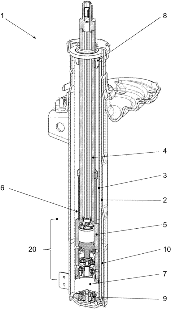
[0042] figure 1 An exemplary embodiment of a shock absorber 1 is shown, which is designed as a semi-active twin-tube damper for a wheel suspension of a motor vehicle.

[0043] The shock absorber 1 has an outer container 2, preferably a container tube, into which an inner tube 3 is inserted.

[0044] The inner tube 3 is cylindrical and closed at its lower end. A piston rod 4 extends in the inner tube 3 , said piston rod having a piston 5 guided on the inner wall of the inner tube 3 and sealed relative thereto.

[0045] The piston 5 divides the working chamber inside the inner tube 3 into a first working chamber 6 and a second working chamber 7, which are respectively filled with a damping medium, such as hydraulic oil. In order to define the upper first working chamber 6 , the inner tube 3 is closed by a piston rod guide 8 , which is supported on the upper end of the inner tube 3 .

[0046] The piston rod guide 8 has an opening for the passage of the piston rod 4 . In addit...


PUM


Abstract

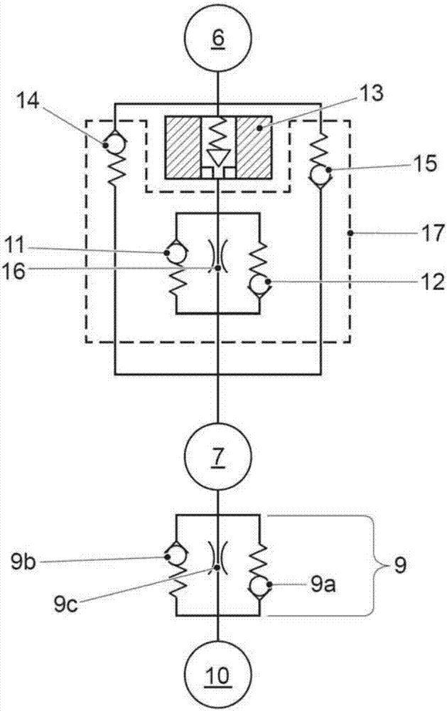
The invention relates to a valve piston arrangement(20) for a vibration damper(1) has an electrically controllable valve(13) for regulating flow and a hydraulic valve unit(17), which includes at leastone hydraulic valve(11,12) and is hydraulically connected in series to the electrically controllable valve(13). The electrically controllable valve(13) and the at least one hydraulic valve(11,12) ofthe hydraulic valve unit are surrounded by a shared housing(21), which is provided for arrangement on a piston rod(4) of the vibration damper(1). The housing(21) forms at least one first opening(23) for communication with a first working chamber(6) of vibration damper(1) and at least one second opening(24) for communication with a second working chamber(7) of vibration damper(1). A flow path(A) between the at least one first opening(23) and the at least one second opening(24) is guided within the shared housing over the electrically controllable valve(13) and the at least one hydraulic valve(11,12) of the hydraulic valve unit(17).

Description

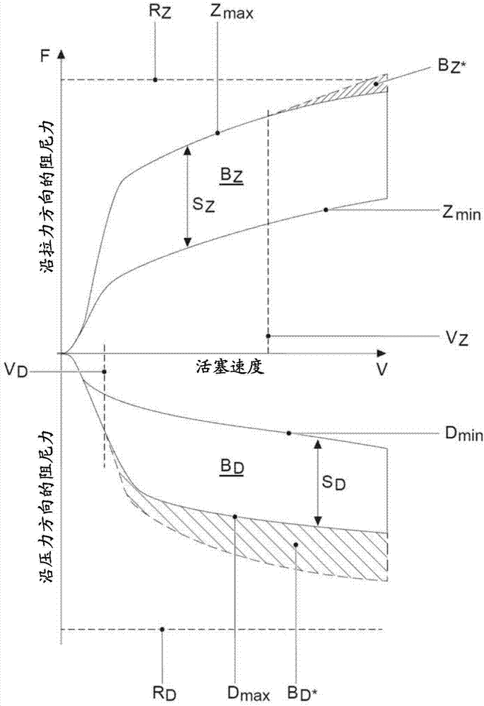
technical field [0001] The invention relates to the field of controllable shock absorbers and in particular to the field of semi-active shock absorbers. The invention relates primarily to a valve-piston arrangement for a shock absorber comprising an electrically controlled valve for regulating the flow and a hydraulic valve arrangement having at least one hydraulic valve hydraulically connected in series with the regulating valve connect. Background technique [0002] Shock absorbers are used in the wheel suspension of automobiles to support axle components on the vehicle structure and dampen their movement. [0003] The damping characteristic of such a shock absorber, that is to say its characteristic curve (damping force as a function of piston speed) can be varied in tension and pressure stages by means of switches and control systems. [0004] In contrast to passive shock absorbers, controllable shock absorbers allow the damping rate of the shock absorber to be varied ...

Claims


Application Information

Patent Timeline
Patent Type & Authority Applications(China)
IPC IPC(8): F16F9/34F16F9/32F16F9/46
CPCF16F9/3207F16F9/3214F16F9/34F16F9/46F16F9/469F16F9/10F16F9/325F16F9/3405
Inventor M.利迪克S.瓦尔K-U.坦克J-R.施莱格尔S.弗洛特曼
Owner VOLKSWAGEN AG
Learn More