Multifunctional portable laser lighting system and laser flashlight

A laser lighting, portable technology, applied in the field of flashlights, can solve the problems of poor design of secondary optics, short illumination distance, single light source function, etc.

Pending Publication Date: 2019-10-22
GUANGZHOU UNIONLUX ELECTRONICS TECH CO LTD
View PDF0 Cites 3 Cited by
  • Summary
  • Abstract
  • Description
  • Claims
  • Application Information

AI Technical Summary

Problems solved by technology

However, due to its application in the field of flashlights, it requires extremely high requirements for portability. Whether it is traditional halogen lamps or LED light sources, they all have limitations in portable lighting due to their own defects, such as short life of bulbs and low brightness. LED is used as a surface light source, the secondary optics are not well designed, the irradiation distance is not far, and the functions of the two light sources are very single, so they can only be used as a portable lighting system

Method used


Image

  • Multifunctional portable laser lighting system and laser flashlight
  • Multifunctional portable laser lighting system and laser flashlight
  • Multifunctional portable laser lighting system and laser flashlight

Examples


Embodiment 1

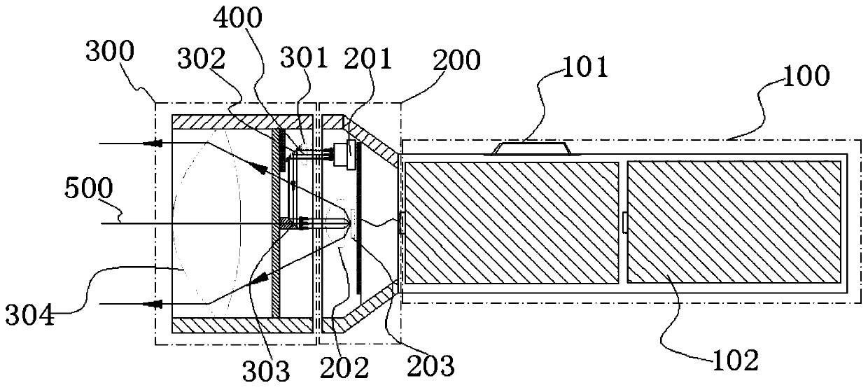
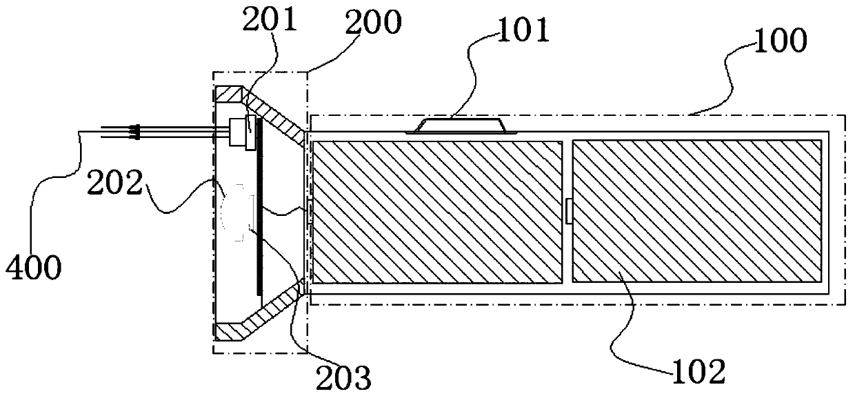
[0030] Such as Figure 1 to Figure 3 As shown, the present invention provides a multifunctional portable laser lighting system, including a first optical system 200 and a second optical system 300; the first optical system 200 is provided with a laser 201 for emitting excitation light, and the first optical system 200 or the second optical system 300 is provided with a wavelength conversion device 203 for absorbing part of the excitation light to form the received light; the second optical system 300 is located at the outermost part of the light emission direction, and the first optical system 200 and the second optical system 300 can generate Relative displacement or relative separation; when there is no displacement or separation between the two optical systems, the illumination light synthesized by the laser light and the excitation light not absorbed by the wavelength conversion device 203 is emitted by the second optical system 300; when the two optical systems are relativ...

Embodiment 2

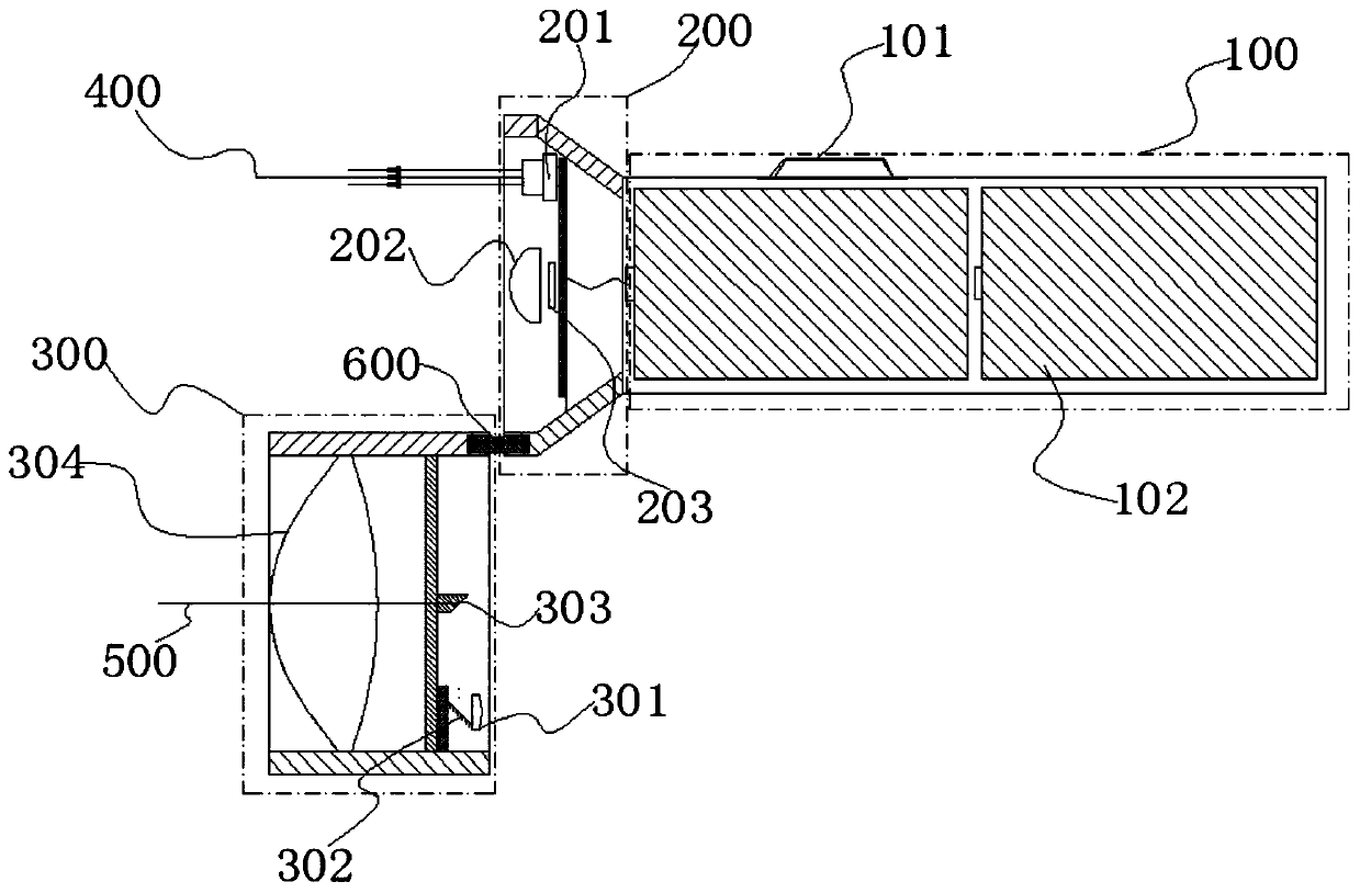
[0045] The difference between Embodiment 2 and Embodiment 1 is: 1. The specific setting position and specific structure of the wavelength conversion device 203 are different. The optical path in Embodiment 1 is mainly based on reflection to reduce the absolute length of the optical path. Embodiment 2 is mainly based on transmission. To simplify the structure of the optical path; 2. The specific location of the first small lens 301 is different; 3. The specific location of the second small lens 202 is different; 4. The connection methods of the first optical system 200 and the second optical system 300 are different.

[0046] Specifically, such as Figure 4 As shown, the first optical system 200 is provided with the laser 201, and the second optical system 300 is provided with a wavelength conversion device 203, and the wavelength conversion device 203 is a transmission structure; the optical axis of the excitation light emitted by the laser 201 and the illumination The exit op...


PUM


Abstract

The invention relates to a multifunctional portable laser lighting system and a laser flashlight. The lighting system comprises a first optical system and a second optical system. A laser for emittingexciting light and a wavelength conversion device for absorbing a part of the exciting light to form excited light are arranged in the first optical system or the second optical system. The second optical system is arranged at an outermost part of a light emitting direction. The first optical system and the second optical system can be relatively displaced or separated. When the two optical systems are not displaced or separated, lighting light synthesized by the excited light and the exciting light which is not absorbed by the wavelength conversion device is emitted by the second optical system. When the two optical systems are relatively displaced or separated, the exciting light emitted by the laser is emitted from the first optical system. Through judgment of whether the two optical systems are relatively displaced or separated, free switching of the functions of emitting lighting light or exciting light by the lighting system is realized, thereby achieving efficient ultra-long-distance lighting and ultra-long-distance call for help or fire making.

Description

technical field [0001] The invention relates to the technical field of flashlights, and more specifically, to a multifunctional portable laser lighting system and a laser flashlight. Background technique [0002] Handheld lighting equipment, also known as a flashlight, is widely used in many outdoor and other special applications due to its very good portability and mobility, such as outdoor mountaineering, exploration, police search and rescue, small space lighting and other scenes. [0003] This hand-held lighting device usually consists of a cylinder body and a cylinder head. The cylinder body has a built-in power supply battery, and the cylinder head is provided with a specific light-emitting device. The most traditional light-emitting devices used in flashlights are low-power halogen bulbs. This type of light source has good color rendering, but has no advantages in brightness and efficiency, and its short life is its fatal shortcoming. The second is the semiconductor ...

Claims


Application Information

Patent Timeline
Patent Type & Authority Applications(China)
IPC IPC(8): F21L4/00F21V9/00F21V14/02F21V13/08F21Y115/30
CPCF21L4/00F21V9/00F21V13/08F21V14/02F21Y2115/30
Inventor 黄成李秀斌陈国平郑治国
Owner GUANGZHOU UNIONLUX ELECTRONICS TECH CO LTD
Why Eureka
Try Eureka