Vision correction device

A vision correction and beam technology, applied in the optical field, can solve problems such as thickness and aberration, achieve aberration-free imaging, avoid the dependence of lens thickness, and widen the range of vision adjustment.

Active Publication Date: 2019-10-22
SHENZHEN LUBANG TECH CO LTD
View PDF5 Cites 2 Cited by
  • Summary
  • Abstract
  • Description
  • Claims
  • Application Information

AI Technical Summary

Problems solved by technology

[0003] The purpose of the present invention is to disclose a vision correction device to solve the ...

Method used


Image

  • Vision correction device
  • Vision correction device
  • Vision correction device

Examples


Embodiment 1

[0028] This embodiment discloses a vision correction device, comprising: a linear polarizer with a common optical axis, a geometric phase lens, and a 1 / 4 wave plate located between the linear polarizer and the geometric phase lens.

[0029] The geometric phase lens of this embodiment is used to realize:

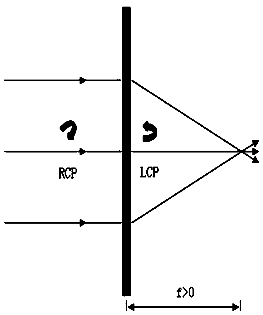
[0030] Such as figure 1 As shown, it is equivalent to the convex lens converging the non-zero same-order diffracted beam with a real focus, and / or

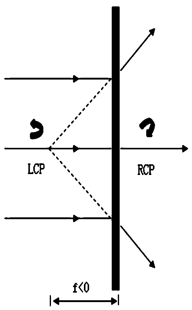
[0031] Such as figure 2 As shown, it is equivalent to the divergence of non-zero diffraction beams of the same order by a concave lens with a virtual focal point.

[0032] Among them, when the light beam is converged, it can be used as farsighted glasses. When the light beam is diverged, it is used as myopia glasses.

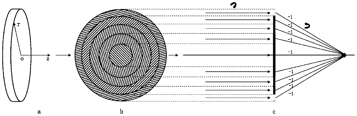
[0033] In this embodiment, the geometric phase lens controls the change of the long-axis direction of the birefringent material corresponding to each ring with the optical axis as the center, so as to perform ...


PUM


Abstract

The invention relates to the technical field of optics, discloses a vision correction device, and aims at solving the inherent defects of the traditional vision correction device such as thick and heavy device and aberration. The device comprises a common optical axis linear polarizer, a geometric phase lens and a 1/4 wave plate which is arranged between the linear polarizer and the geometric phase lens. The geometric phase lens realizes the beam diffraction and deflection by controlling the change of the long-axis direction of the birefringent material corresponding to each ring with the optical axis as the center so as to realize the convergence of the same-order diffracted beam equal to the non-zero diffracted beam by the convex lens with the real focus and/or divergence of the same-order diffracted beam equal to the non-zero diffracted beam by the concave lens with the virtual focus.

Description

technical field [0001] The invention relates to the field of optical technology, in particular to a vision correction device. Background technique [0002] The core principle of the vision correction device is to diverge or focus the ambient light incident on the human eye to a certain extent through the optical system, so that the imaging beam can finally focus on the retina of the human eye. Existing technical solutions for vision correction generally use traditional curved concave / convex lenses to realize the divergence / focus of light beams. The disadvantages are: 1. The lens is thick and heavy, especially for high myopia above 1000 degrees. It reaches about 10mm; 2. The curved lens is not an ideal optical system, and it cannot form a perfect image. There must be aberrations, which makes the scene perceived by the human eye deviate from the reality. Contents of the invention [0003] The purpose of the present invention is to disclose a vision correction device to solv...

Claims


Application Information

Patent Timeline
IPC IPC(8): G02C7/12G02C7/10
CPCG02C7/10G02C7/12
Inventor 陈琪张礼朝李晓春
Owner SHENZHEN LUBANG TECH CO LTD
Why Eureka
Try Eureka