Wind driven generator liquid cooling device and wind driven generator comprising same

A technology for wind turbines and generators, applied in the field of wind turbines and wind turbine liquid cooling devices, can solve problems such as corrosion of motor structural parts, reduction of the life of key components such as insulation, and easy leakage of liquid cooling, so as to reduce the impact. Effect

Active Publication Date: 2019-10-22
ZHEJIANG UNIV +1
View PDF5 Cites 4 Cited by
  • Summary
  • Abstract
  • Description
  • Claims
  • Application Information

AI Technical Summary

Problems solved by technology

[0003] The technical problem to be solved by the present invention is to overcome the defects in the prior art that the liquid cooling of the wind power generator is easy to leak, cause corrosion of the motor structural parts, and reduce the life of key components such as insulation, and provide a liquid cooling device for the wind power generator and including its wind turbines

Method used


Image

  • Wind driven generator liquid cooling device and wind driven generator comprising same
  • Wind driven generator liquid cooling device and wind driven generator comprising same
  • Wind driven generator liquid cooling device and wind driven generator comprising same

Examples


Embodiment 1

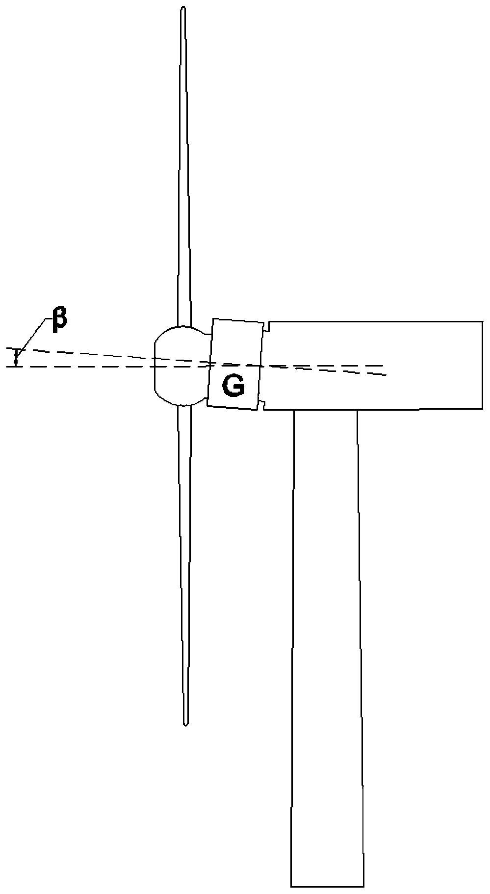
[0034] Such as Figure 1-Figure 4 As shown, this embodiment discloses a wind power generator, which includes a liquid cooling device for the wind power generator. The wind power generator liquid cooling device of this embodiment includes a generator G and a liquid cooling pipe 3 . Wherein, the generator G includes a driving end and a non-driving end, and the generator G is inclined relative to the horizontal plane so that the driving end is higher than the non-driving end. Among them, such as figure 1 As shown, the generator G forms an angle β with the horizontal plane. The size of the included angle β can be determined according to actual application conditions.

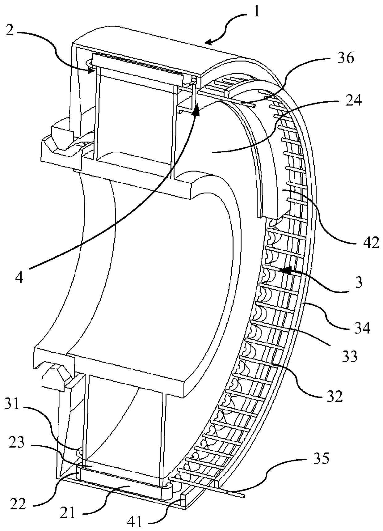
[0035] Such as figure 2 , image 3 and Figure 4 As shown, the liquid cooling device of the wind power generator in this embodiment also includes a liquid cooling pipe 3 for cooling liquid, the liquid cooling pipe 3 is arranged in the generator G, and the connection 33 of the liquid cooling pipe 3 is arranged...

Embodiment 2

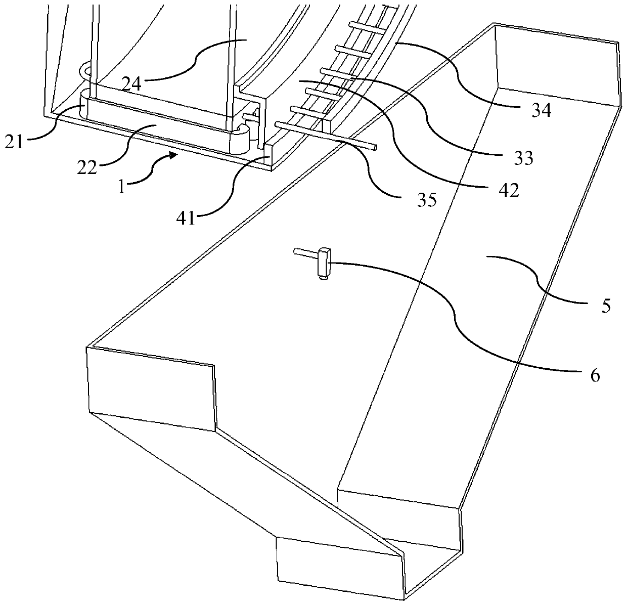
[0050] Such as Figure 5 and Figure 6 As shown, this embodiment discloses another liquid cooling device for wind power generators. Wherein, the generator of this embodiment further includes a stator 2 and a rotor 1 , and the sealing assembly 4 further includes a moving end 41 and a stationary end 42 . Wherein, the moving end 41 is connected to the rotor 1 , and the stationary end 42 is connected to the stator 2 , and the moving end 41 and the stationary end 42 cooperate with each other to form a seal. The sealing assembly 4 is divided into a stationary end 42 and a moving end 41 respectively connected to the stator 2 and the rotor 1 , so that the sealing assembly 4 does not interfere with the relative movement between the stator 2 and the rotor 1 while completing the sealing.

[0051] Such as Figure 5 and Figure 6 As shown, the moving end 41 in this embodiment extends around the circumference of the rotor 1, and the stationary end 42 extends around the circumference of ...


PUM


Abstract

The invention discloses a wind driven generator liquid cooling device and a wind driven generator comprising the same. The wind driven generator liquid cooling device comprises a generator which comprises a driving end and a non-driving end and is obliquely arranged relative to a horizontal plane so that the driving end is higher than the non-driving end; and liquid cooling pipes arranged in the generator, wherein the joints of the liquid cooling pipes are arranged at the non-driving end. According to the invention, the generator is obliquely mounted, and the connecting parts which easily suffer from leakage are arranged at the non-driving end of the generator, so that the influence of liquid leakage on the generator is reduced. In addition, a water collecting disc and an accumulated liquid monitoring device are further arranged, so leakage of the cooling liquid can be found in time, and the defect that it is difficult to carry out judgment from the flow of a cooling liquid loop or thereading number of a pressure sensor when a small amount of leakage occurs is overcome.

Description

technical field [0001] The invention relates to a liquid cooling device for a wind power generator and a wind power generator including the same. Background technique [0002] The heat generated during the operation of the wind turbine must be dissipated by effective means to ensure the long-term reliable operation of the generator. The cooling efficiency of liquid cooling is significantly higher than that of air cooling, but its application in wind turbines is relatively limited, mainly because its reliability is lower than that of traditional air cooling. After long-term operation of liquid cooling, leakage problems are prone to occur, especially for the harsh environment and difficult maintenance of the fan operation, the probability of these problems is greatly increased. Leakage of coolant will not only cause the pressure drop of the cooling circuit and weaken the cooling effect, but more seriously, it may cause corrosion of structural parts and even reduce the life of...

Claims


Application Information

Patent Timeline
Patent Type & Authority Applications(China)
IPC IPC(8): H02K1/20H02K9/19H02K11/20
CPCH02K1/20H02K9/19H02K11/20Y02E10/72
Inventor 闻汇吴立建施杨崔明方攸同
Owner ZHEJIANG UNIV
Why Eureka
Try Eureka