Shaft end generator for railway wagon

A technology for railway freight cars and generators, applied in railway car body parts, railway transportation, railway transportation, etc., can solve the problems of inapplicability of the three-piece bogie shaft end power generation scheme, troubled power supply reliability, and poor power supply reliability. , to achieve high reliability, improve protection ability, and make small changes.

Active Publication Date: 2019-10-22
CSR ZHUZHOU ELECTRIC LOCOMOTIVE RES INST
View PDF7 Cites 8 Cited by
  • Summary
  • Abstract
  • Description
  • Claims
  • Application Information

AI Technical Summary

Problems solved by technology

[0002] With the expansion of the operation scale of railway freight trains and the service area of ​​special vehicles, more and more monitoring or protection devices (such as electronic anti-skid devices, braking systems, axle temperature detection equipment, etc.) are widely used in the safety system of railway freight trains , and the power supply reliability of these devices has been perplexing the application of the safety system of railway freight trains. The traditional power supply method is that the locomotive supplies power to each freight car through cables. Due to the frequent marshalling of railway freight trains and the harsh operating environment, the power supply is reliable Therefore, it is a very marketable application research to install a power generation device separately on the railway freight car to solve the power consumption problem of the railway freight train safety system.
However, since most of the bogies of the existing railway freight cars are three-piece bogies with no axle box structure, the shaft end power generation schemes of the above patents are not applicable to the three-piece bogies.

Method used


Image

  • Shaft end generator for railway wagon
  • Shaft end generator for railway wagon
  • Shaft end generator for railway wagon

Examples


Embodiment Construction

[0021] In order to make the object, technical solution and advantages of the present invention clearer, the present invention will be described in further detail below in conjunction with specific embodiments and with reference to the accompanying drawings.

[0022] It should be noted that all expressions using "first" and "second" in the embodiments of the present invention are to distinguish two entities with the same name but different parameters or parameters that are not the same, see "first" and "second" It is only for the convenience of expression, and should not be construed as a limitation on the embodiments of the present invention, which will not be described one by one in the subsequent embodiments.

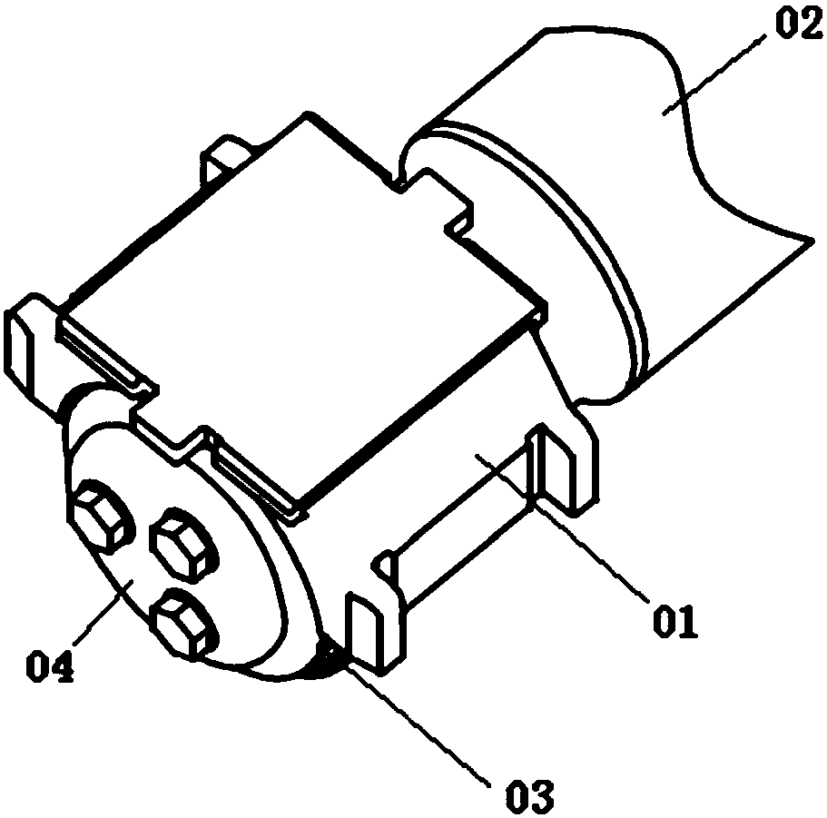
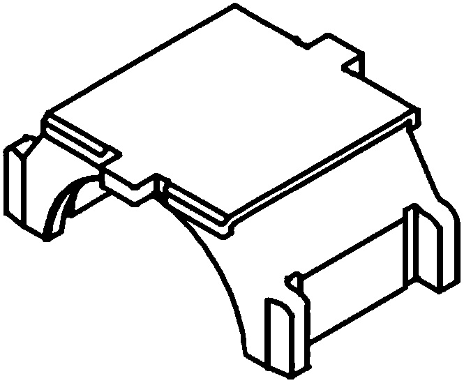
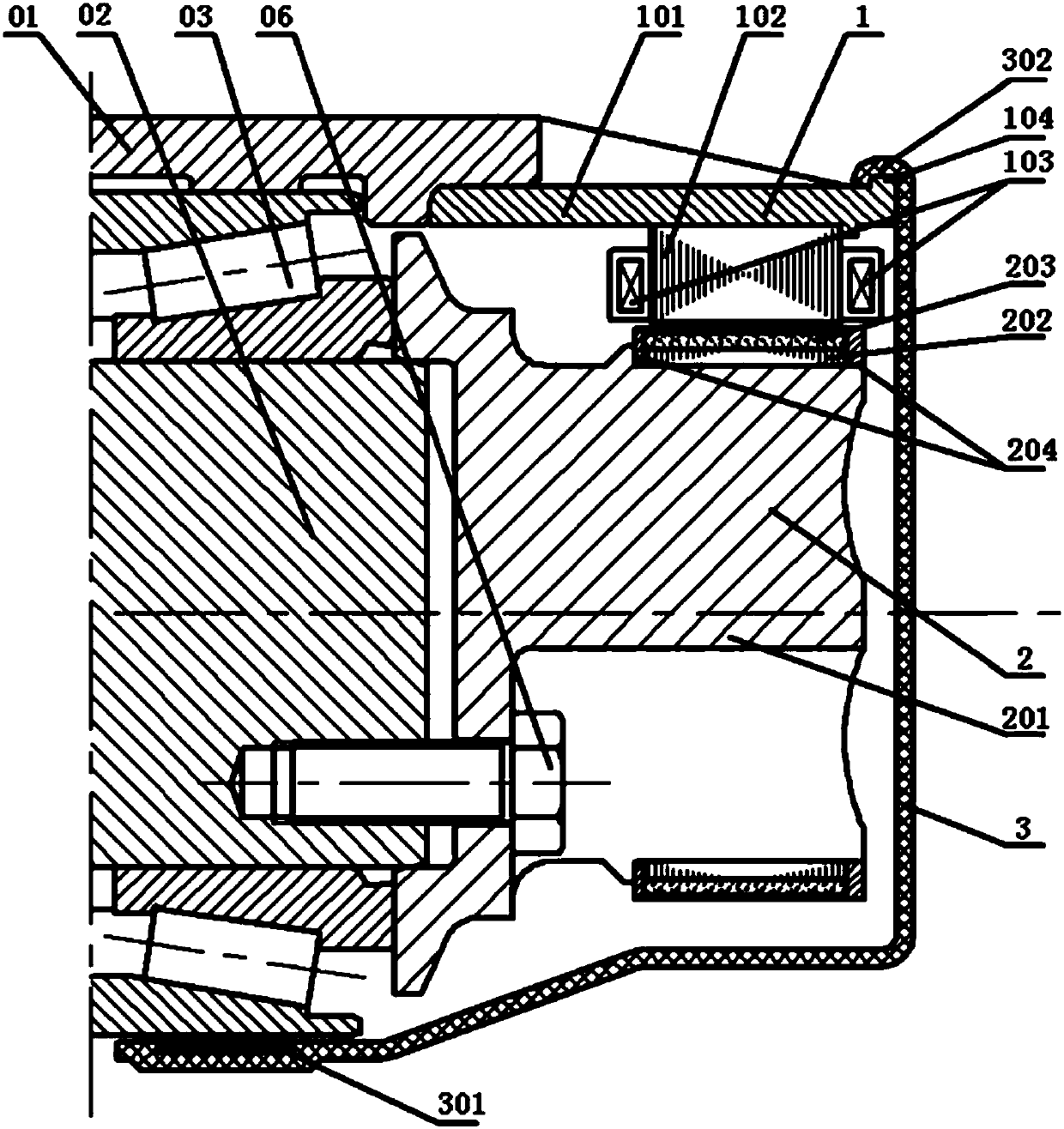
[0023] An embodiment of the present invention provides an axle-end generator for a railway freight car, aiming at solving the technical problem that the axle-end power generation scheme in the prior art cannot be applied to a railway freight car using a three-piece bog...


PUM


Abstract

The invention discloses a shaft end generator for a railway wagon. The shaft end generator comprises a stator, a rotor and a side cover; the stator is a semicircular ring structure matched with a bearing saddle and is arranged on the side surface of the bearing saddle through a shell of a semicircular cylinder structure; the rotor is arranged at the axle end of the axle through a bracket sleeve for replacing a front cover of a bearing; the side cover is arranged on the outer sides of the stator and the rotor; the side cover is in sealing connection with the bearing saddle, the shell and the axle bearing to form a sealing body used for containing the stator and the rotor. The shaft end generator can be applied to a railway wagon using three large-piece bogies, and has the advantages of thehigh reliability, the high protection, the no maintenance and the small bogie change.

Description

technical field [0001] The invention relates to the technical field of railway freight cars, in particular to an axle-end generator for railway freight cars. Background technique [0002] With the expansion of the operation scale of railway freight trains and the service area of ​​special vehicles, more and more monitoring or protection devices (such as electronic anti-skid devices, braking systems, axle temperature detection equipment, etc.) are widely used in the safety system of railway freight trains , and the power supply reliability of these devices has been perplexing the application of the safety system of railway freight trains. The traditional power supply method is that the locomotive supplies power to each freight car through cables. Due to the frequent marshalling of railway freight trains and the harsh operating environment, the power supply is reliable Therefore, it is a very marketable application research to solve the power consumption problem of the railway...

Claims


Application Information

Patent Timeline
Patent Type & Authority Applications(China)
IPC IPC(8): H02K7/00H02K1/12H02K5/04H02K5/16B61D43/00
CPCB61D43/00H02K1/12H02K5/04H02K5/16H02K7/006Y02T30/00
Inventor 李华湘冯守智刘春秀辛本雨杨金霞盛振强胡华吴江权赵安然刘雄
Owner CSR ZHUZHOU ELECTRIC LOCOMOTIVE RES INST
Why Eureka
Try Eureka