Gas density relay with on-line self-calibration function and calibration method thereof
A technology of gas density and relay, applied in the field of electric power, can solve the problems of lowering of insulation strength, flashover, damage and other problems on the surface of insulating parts
- Summary
- Abstract
- Description
- Claims
- Application Information
AI Technical Summary
Problems solved by technology
Method used
Image
Examples
Embodiment 1
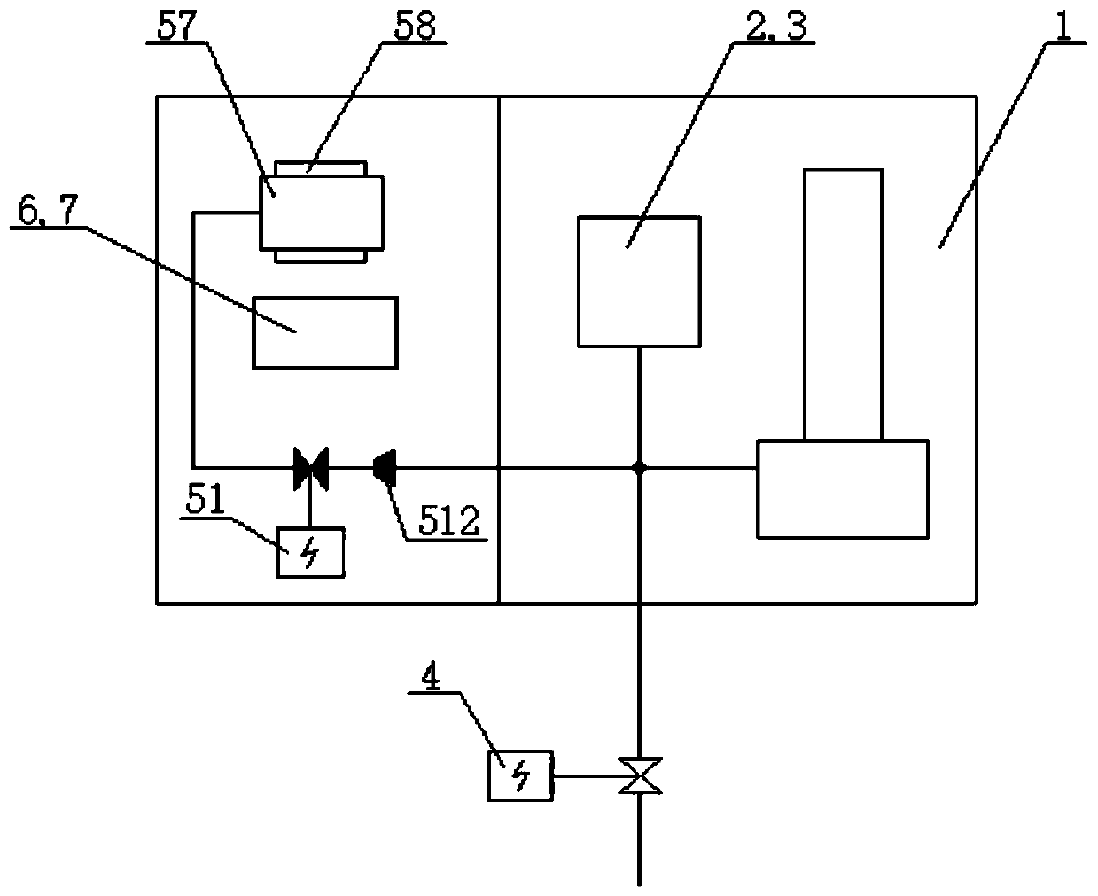
[0118] figure 1 It is a schematic structural diagram of a gas density relay with an on-line calibration function used for high and medium voltage electrical equipment in Embodiment 1 of the present application.
[0119] like figure 1 As shown, a gas density relay with an online verification function includes a gas density relay body 1, and the gas density relay body 1 includes: a housing, and a base, an end seat, and a pressure detector arranged in the housing , temperature compensation components, several signal generators, movement, pointer, dial. One end of the pressure detector is fixed on the base and communicated with it, the other end of the pressure detector is connected to one end of the temperature compensation element through the end seat, and the other end of the temperature compensation element One end is provided with a crossbeam, and the crossbeam is provided with an adjustment piece for pushing the signal generator and making the contacts of the signal genera...
Embodiment 2
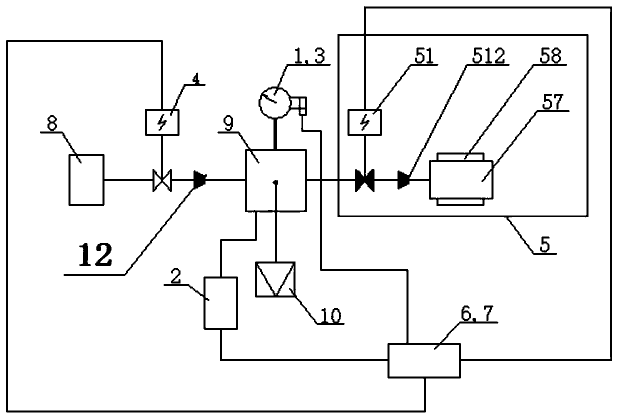
[0140] like figure 2 As shown, a gas density relay or a gas density monitoring device with an online self-checking function provided by Embodiment 2 of the present invention includes: a gas density relay body 1 (the gas density relay body 1 mainly also includes: a housing, and a device base, pressure detector, temperature compensation element, movement, pointer, dial, end seat, several signal generators and electrical equipment connection joints), pressure sensor 2, temperature sensor 3, normally open valve in the housing 4. Normally closed valve 51, air chamber 57, heating element 58, flow controller B 512, flow controller A 12, online verification contact signal sampling unit 6, intelligent control unit 7, multi-way joint 9 and air supply interface 10 . In this embodiment, an air supply interface 10 and a multi-way joint 9 are added. One end of the normally open valve 4 is connected with electrical equipment, and the other end is connected with the flow controller A12, an...
PUM
 Abstract
Description
Claims
Application Information
 - R&D
- Intellectual Property
- Life Sciences
- Materials
- Tech Scout
- Unparalleled Data Quality
- Higher Quality Content
- 60% Fewer Hallucinations
Browse by: Latest US Patents, China's latest patents, Technical Efficacy Thesaurus, Application Domain, Technology Topic, Popular Technical Reports.
© 2025 PatSnap. All rights reserved.Legal|Privacy policy|Modern Slavery Act Transparency Statement|Sitemap|About US| Contact US: help@patsnap.com


