Fixed clamping structure of element box

A technology for fixing cards and component boxes, which is applied to electrical components, chassis/cabinet/drawer parts, electrical equipment shells/cabinets/drawers, etc. Inconvenient disassembly and other problems, to achieve the effect of material saving, convenient operation and easy realization

Pending Publication Date: 2019-10-22
SHANGHAI LEIYUE AUTOMATIC DEVICE
View PDF0 Cites 0 Cited by
  • Summary
  • Abstract
  • Description
  • Claims
  • Application Information

AI Technical Summary

Problems solved by technology

[0002] At present, in the design of electronic products, the housing fixing structure is used to facilitate the disassembly and assembly of movable parts and improve assembly efficiency. There are many kinds of existing housing fixing structures, including direct screw fixing, which is very inconvenient to install and disassemble. , is clamped on the T-shaped slot, although

Method used


Image

  • Fixed clamping structure of element box
  • Fixed clamping structure of element box

Examples


Embodiment Construction

[0014] Objects, advantages and features of the present invention will be illustrated and explained by the following non-limiting description of preferred embodiments. These embodiments are only typical examples of applying the technical solutions of the present invention, and all technical solutions formed by adopting equivalent replacements or equivalent transformations fall within the protection scope of the present invention.

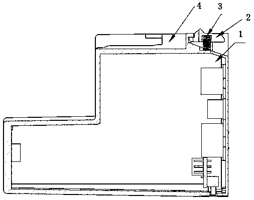
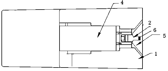
[0015] The invention discloses a fixed clamping structure of a component box, such as figure 1 and figure 2 As shown, the fixed clamping structure is arranged on the component box housing 1, and the fixed clamping structure includes a tongue 2, an elastic member 3, a guide slot 4 and a guide groove 5, the guide slot, the tongue, the guide The grooves are all arranged on the same plane on one side of the component box housing. In this technical solution, the guide slots are preferably C-shaped guide slots, and the guide slots are preferably V-shaped...


PUM


Abstract

The invention discloses a fixed clamping structure of an element box. The fixed clamping structure is arranged on an element box shell and comprises a clamping tongue, an elastic piece, an insertion guiding slot and a direction guiding slot, wherein the insertion guiding slot, the clamping tongue and the direction guiding slot are all arranged on the same plane at one side of the element box shell, the clamping tongue is arranged between the insertion guiding slot and the direction guiding slot, a movable handle of the clamping tongue is consistent with the opening direction of the direction guiding slot, a rotating shaft at the front end of the clamping tongue is consistent with the opening direction of the insertion guiding slot, the insertion guiding slot is provided with a fixing holematched with the rotating shaft at the front end of the clamping tongue, the elastic piece is arranged between the clamping tongue and the element box shell, the elastic piece is arranged below the clamping tongue, and the elastic piece is arranged in a spring slot matched with the elastic piece. The clamping structure is simple, convenient to operate, material-saving and easy to implement, can bewell clamped to various corresponding structures and can realize assembly and disassembly of the shell by the single hand.

Description

technical field [0001] The invention relates to a fixed clamping structure of a component box, which can be used in the technical field of mechanical manufacturing. Background technique [0002] At present, in the design of electronic products, the housing fixing structure is used to facilitate the disassembly and assembly of movable parts and improve assembly efficiency. There are many kinds of existing housing fixing structures, including direct screw fixing, which is very inconvenient to install and disassemble. , It is clamped on the T-shaped slot, although it is easy to install, but it can only be matched with the structure with a T-shaped slot base, and a screwdriver and other tools are required for disassembly. The above-mentioned methods take up a lot of space in the design of the industrial structure and affect the layout of the internal structure of the product, so they are not suitable for promotion and use in the industry. Contents of the invention [0003] Th...

Claims


Application Information

Patent Timeline
IPC IPC(8): H05K5/02
CPCH05K5/0217
Inventor 樊一群李云宏
Owner SHANGHAI LEIYUE AUTOMATIC DEVICE
Why Eureka
Try Eureka