Gas distribution valve and gas catalytic converter using same

A gas separation valve and catalytic converter technology, applied in chemical instruments and methods, gas treatment, separation methods, etc., can solve problems such as difficulties in later expansion, and achieve the effect of reducing maintenance costs, ensuring processing efficiency, and ensuring purification quality.

Inactive Publication Date: 2019-10-25
CHONGQING YIXI BRAND PLANNING CO LTD
View PDF0 Cites 0 Cited by
  • Summary
  • Abstract
  • Description
  • Claims
  • Application Information

AI Technical Summary

Problems solved by technology

[0005] 2. The processing capacity of the equipment is pre-designed, and it is very difficult to expand in the later stage. Generally, multiple devices can only be used in parallel at the same time or replaced with devices with a larger processing capacity. How to distribute the exhaust gas to each processing device when multiple devices are used in parallel is also currently unknown. solved problem

Method used


Image

  • Gas distribution valve and gas catalytic converter using same
  • Gas distribution valve and gas catalytic converter using same
  • Gas distribution valve and gas catalytic converter using same

Examples


Embodiment Construction

[0053] The following will clearly and completely describe the technical solutions in the embodiments of the present invention with reference to the drawings in the embodiments of the present invention.

[0054] In describing the present invention, it should be understood that the terms "upper", "lower", "front", "rear", "left", "right", "top", "bottom", "inner", " The orientation or positional relationship indicated by "outside", etc. is based on the orientation or positional relationship shown in the drawings, and is only for the convenience of describing the present invention and simplifying the description, rather than indicating or implying that the referred device or element must have a specific orientation, so as to Specific orientation configurations and operations, therefore, are not to be construed as limitations on the invention.

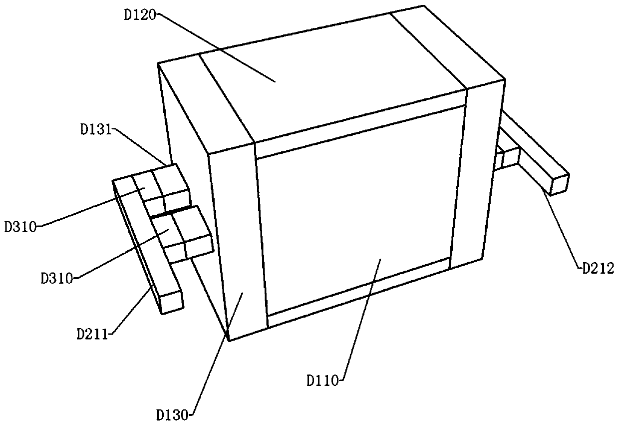
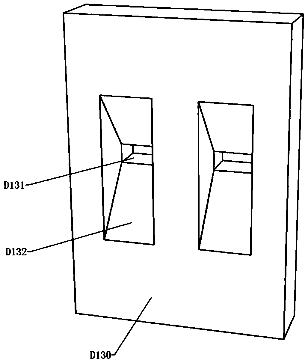
[0055] see Figure 1-Figure 19 , the gas catalytic converter of this embodiment includes a placement frame, a catalytic module, and a ga...


PUM


Abstract

The invention discloses a gas distribution valve and a gas catalytic converter using the same. The gas catalytic converter comprises a placement frame, catalytic modules and gas distribution valves, wherein the placement frame comprises two sealing covers, two side plates and two flat plates; two flat plates are separately and fixedly assembled at two ends of two side plates; two sealing covers are assembled at the opening ends of a placement chamber enclosed by two side plates and two flat plates in a sealed manner; the placement chamber is provided with at least one partition plate; two endsof the partition plate are separately and fixedly assembled on two flat plates in a sealed manner, so the placement chamber is divided into a plurality of compartments; at least one catalytic moduleis arranged in each compartment; the positions, corresponding to the compartments, of each sealing cover are provided with flow-guiding grooves; the cross section area of each flow-guiding groove is gradually reduced from one end close to the catalytic modules to the other end; meanwhile, the position, located at the outer side of each sealing cover, of the end with a minimum cross section area ofeach flow-guiding groove is provided with a pipe joint; a pipe joint arranged on one of the sealing covers communicates with a first exhaust connector of a gas distribution valve; and the gas distribution inlets of the gas distribution valves respectively communicate with a gas inlet pipe.

Description

technical field [0001] The invention relates to an organic waste gas treatment technology, in particular to a gas distribution valve and a gas catalytic converter thereof. Background technique [0002] It is a very mature theory and technology to irradiate organic waste gas with ultraviolet light to catalyze the decomposition of organic matter in organic waste gas into inorganic matter. At present, the main method is to install ultraviolet lamp tubes in the airflow channel, and emit ultraviolet light of different wavelengths through the ultraviolet lamp tubes, which are irradiated in the airflow, so that the organic matter in the airflow is catalyzed into inorganic matter in a few seconds, so as to achieve purification Effect. [0003] During the process of researching the existing relevant designs, the applicant found that the current similar equipment mainly has the following problems: [0004] 1. The outside of the ultraviolet lamp needs to be cleaned regularly to preve...

Claims


Application Information

Patent Timeline
IPC IPC(8): B01D53/86B01D53/44
CPCB01D53/8687B01D2259/804
Inventor 李子喜
Owner CHONGQING YIXI BRAND PLANNING CO LTD
Why Eureka
Try Eureka