Clamp for static blade milling total length machining

A static blade, total length technology, applied in the direction of manufacturing tools, metal processing equipment, metal processing machinery parts, etc., can solve the problems of high equipment input cost, waste of resources, long manufacturing cycle and so on

Pending Publication Date: 2019-10-25
WUXI AIERFU BLADE
View PDF0 Cites 4 Cited by
  • Summary
  • Abstract
  • Description
  • Claims
  • Application Information

AI Technical Summary

Problems solved by technology

[0003] For the processing of blades with different total lengths in the prior art, different special fixtures should be used for clamping, which will not only consume a lot of manpower, equipment, materials and other resources, but also cause high equipment investment costs and long manufacturing cycles. It m...

Method used


Image

  • Clamp for static blade milling total length machining
  • Clamp for static blade milling total length machining
  • Clamp for static blade milling total length machining

Examples


Embodiment Construction

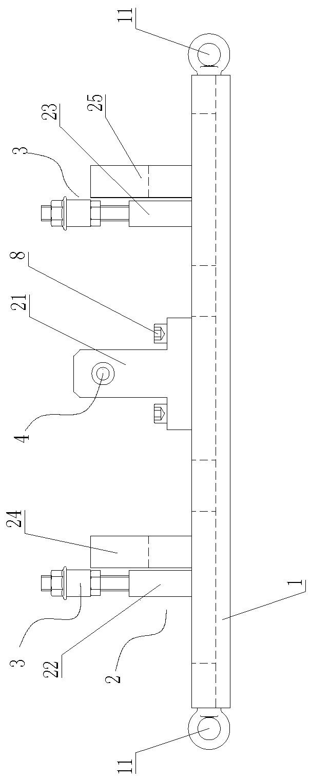
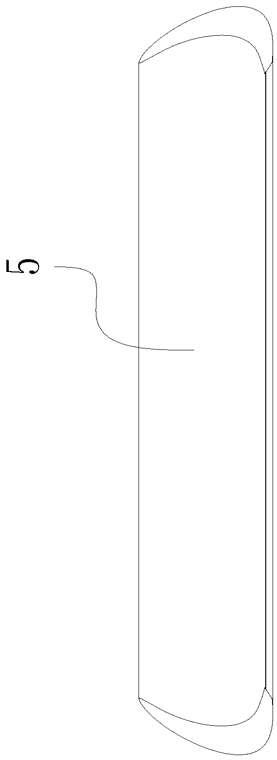
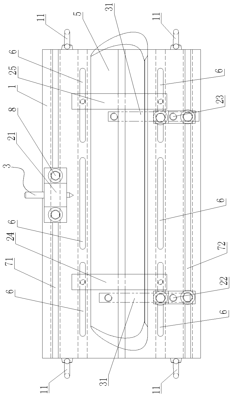
[0014] See Figure 1 to Figure 4 , a fixture for milling the overall length of a stationary blade, which includes a bottom plate 1, on which a blade profile positioning assembly 2, a tip positioning device 4, and a blade pressing device 3 are arranged, and the blade profile positioning assembly 2 includes three. Triangularly arranged support blocks: support block one 21, support block two 22, support block three 23 and two profile positioning blocks arranged in parallel: profile positioning block one 24, profile positioning block two 25, profile positioning block one 24. Profile positioning block 2 25 corresponds to the end faces on both sides of the blade 5 respectively, support block 1 21 is located at the top corner of the triangle, support block 2 22 and support block 3 23 are respectively located at the two feet of the triangle; There are at least two groups of waist-shaped holes 6 arranged in parallel. The waist-shaped holes 6 are arranged along the strip length directio...


PUM


Abstract

The invention discloses a clamp for static blade milling total length machining. By means of the clamp, manpower, equipment, materials and other resources can be saved, the equipment input cost can bereduced, the manufacturing and machining period is shortened, and resource waste can be effectively avoided. The clamp comprises a bottom plate, and the bottom plate is provided with a blade profilepositioning assembly, a tip positioning device and a blade pressing device. The blade profile positioning assembly comprises three supporting blocks which are arranged in a triangle manner and includethe first supporting block, the second supporting block and the third supporting block, and two parallel profile positioning blocks including the first profile positioning block and the second profile positioning block. The first profile positioning block and the second profile positioning block correspond to the two side end faces of a blade correspondingly. The bottom plate is provided with atleast two sets of parallel kidney-shaped holes arranged in the strip length direction of the bottom plate, and the first profile positioning block and the second profile positioning block are fixed inthe kidney-shaped holes in the two sides correspondingly.

Description

technical field [0001] The invention relates to the technical field of stationary vane processing equipment, in particular to a fixture for milling the overall length of a stationary vane. Background technique [0002] The diaphragms in steam turbines are generally stationary blades. In the practical application of aviation and power generation products, there is less demand for large and medium-sized stationary blades with constant cross-sections, and there is no need for mass production, and the total length of each set of large and medium-sized stationary blades is different. , but in the process of processing large and medium-sized stationary blades with constant variable cross-sections of different lengths, the clamping of each set of large and medium-sized stationary blades needs to be realized with a special fixture, and each set of large and medium-sized stationary blades needs to be designed and manufactured separately. Fixtures will not only consume a lot of manpow...

Claims


Application Information

Patent Timeline
IPC IPC(8): B23Q3/06
CPCB23Q3/063
Inventor 鲍伟新郑兰兰
Owner WUXI AIERFU BLADE
Why Eureka
Try Eureka