
Filter cloth positioning and cutting device

A filter cloth and cutting technology, applied in metal processing and other directions, can solve the problems of easy occurrence of burrs, no dust collection, and reduced device practicability, etc., to improve the processing environment, improve the cutting effect, and improve the practicability.

Inactive Publication Date: 2019-10-25
淮北雷德机电科技有限公司
View PDF9 Cites 5 Cited by
  • Summary
  • Abstract
  • Description
  • Claims
  • Application Information

AI Technical Summary

Problems solved by technology

[0003] However, there are still relatively obvious defects in its use: 1. The positioning function of the above-mentioned device to the filter cloth raw material is not perfect. When one side of the filter cloth is cut, and then the other side is cut, the filter cloth It is often deformed and tilted by the cutting knife, making the other side not only inconvenient to cut, but also prone to burrs; 2. The dust-proof effect of the above-mentioned device is not good, and it does not have the function of dust collection, which is inconvenient for people use, which reduces the usefulness of the device

Method used

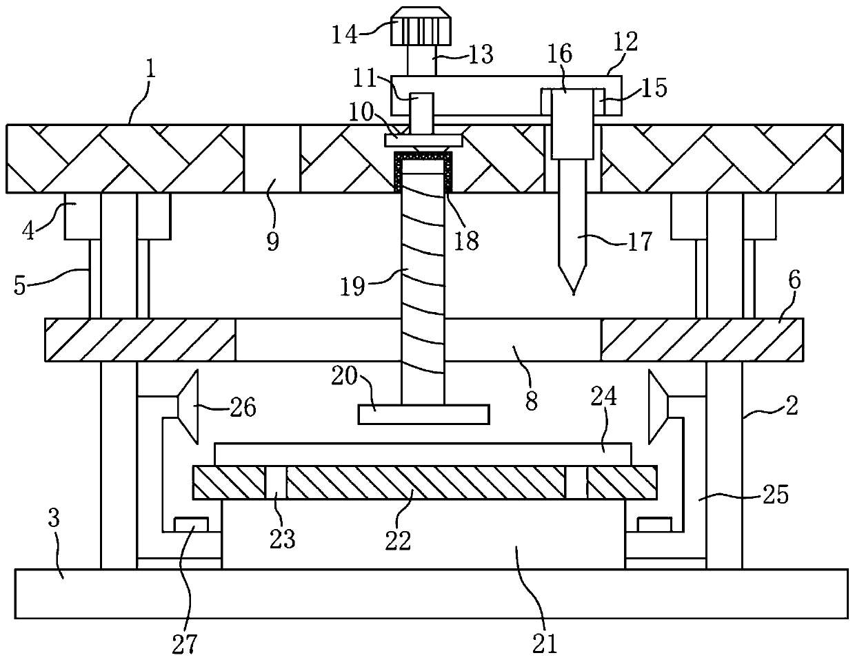

Image

  • Filter cloth positioning and cutting device
  • Filter cloth positioning and cutting device
  • Filter cloth positioning and cutting device

Examples


Embodiment Construction

[0020] The following will clearly and completely describe the technical solutions in the embodiments of the present invention with reference to the accompanying drawings in the embodiments of the present invention. Obviously, the described embodiments are only some, not all, embodiments of the present invention. Based on the embodiments of the present invention, all other embodiments obtained by persons of ordinary skill in the art without making creative efforts belong to the protection scope of the present invention.

[0021] see Figure 1-3 , the present invention provides a technical solution:

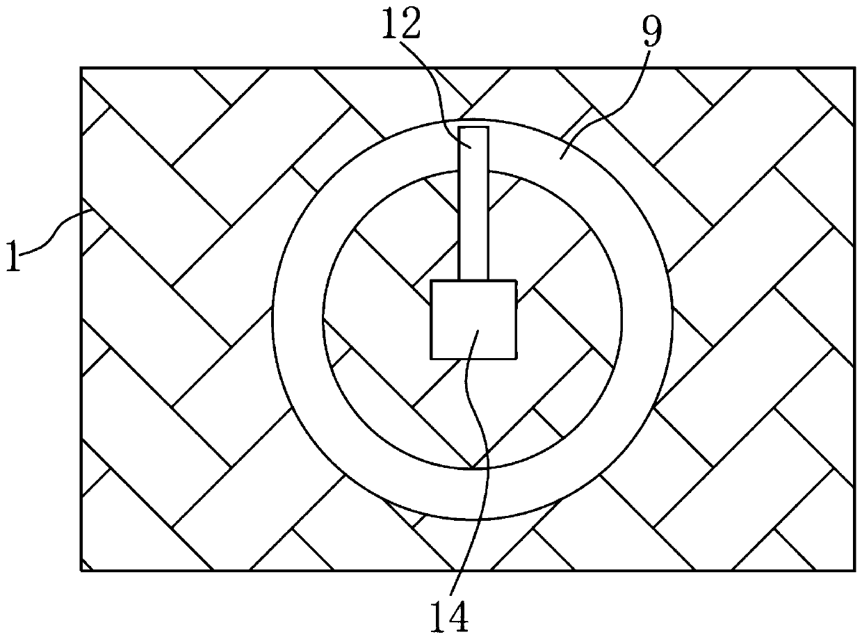
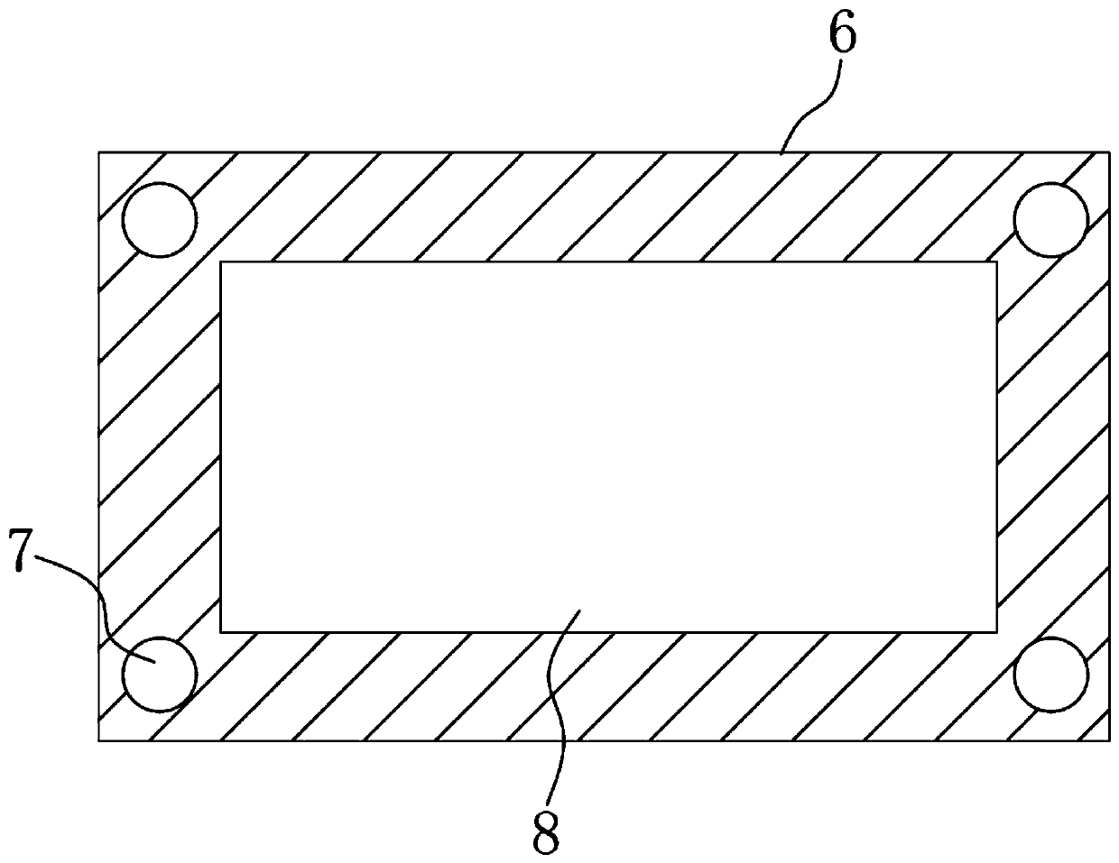
[0022] A filter cloth positioning and cutting device, comprising a top plate 1, a guide column 2 is symmetrically fixed on the top plate 1, a bottom plate 3 is fixedly installed on the end of the guide column 2 away from the top plate 1, and a motor 4 is symmetrically fixed on the top plate 1, and the motor 4 Other models such as Y90S-2 can be used. The output end of the motor 4 i...


PUM


Abstract

The invention discloses a filter cloth positioning and cutting device. The filter cloth positioning and cutting device comprises a top plate, wherein guide columns are symmetrically and fixedly arranged on the top plate, and symmetrical hydraulic cylinders are fixedly connected to a positioning plate; an annular groove is formed in the top plate, a rotating shaft is fixedly arranged on the side, far away from the top plate, of a rotating rod, a lifting air cylinder is fixedly arranged in an installing groove, and a cutting knife is arranged on the lifting air cylinder; and a threaded hole is formed in the side, opposite to a limiting plate, of the center of the top plate, a threaded rod is movably arranged in the threaded hole, and a central pressing plate is fixedly arranged at the end, far away from the threaded hole, of the threaded rod. According to the filter cloth positioning and cutting device, the structure for double fixing and pressing an outer layer and the center of a filter cloth raw material is arranged in the device, so that the side edge of to-be-cut filter cloth is always in the straining state, the condition that the filter cloth subject to partial side edge cutting is inclined, so that cutting of the residual side edge is influenced is avoided, meanwhile, a dust collection device and a dust suction device are arranged in a built-in mode, and the dust prevention effect is good.

Description

technical field [0001] The invention relates to the technical field of filter cloth processing, in particular to a filter cloth positioning and cutting device. Background technique [0002] In the prior art, a sewage treatment filter cutting device with the application number "201720834352.6" includes a workbench, the upper surface of the workbench is provided with a door-shaped mounting frame at the rear end, and the lower surface of the beam of the door-shaped mounting frame is provided with a There is a slide rail, and an electric trolley is arranged inside the slide rail. The lower surface of the electric trolley is provided with a No. 1 hydraulic cylinder with the telescopic end facing downward. The telescopic end of the No. 1 hydraulic cylinder is provided with a rotating motor whose rotating end is horizontal , the rotary end of the rotating motor is set with a blade, the upper surface of the workbench and the front and rear sides of the door-shaped mounting frame are...

Claims


Application Information

Patent Timeline
IPC IPC(8): B26D1/28B26D7/02B26D7/18
CPCB26D1/285B26D7/025B26D7/1863B26D2007/0018
Inventor 吴义成李洋
Owner 淮北雷德机电科技有限公司
Learn More