Material taking and placing device, robot and taking and placing method
A technology for picking and placing devices and materials, which is applied in storage, transportation, and packaging. It can solve the problems of large space, limited use, and cumbersome steps for picking and placing materials, and achieves simple steps, flexible shapes, and reduced space occupied by the site. Effect
- Summary
- Abstract
- Description
- Claims
- Application Information
AI Technical Summary
Problems solved by technology
Method used
Image
Examples
Embodiment 1
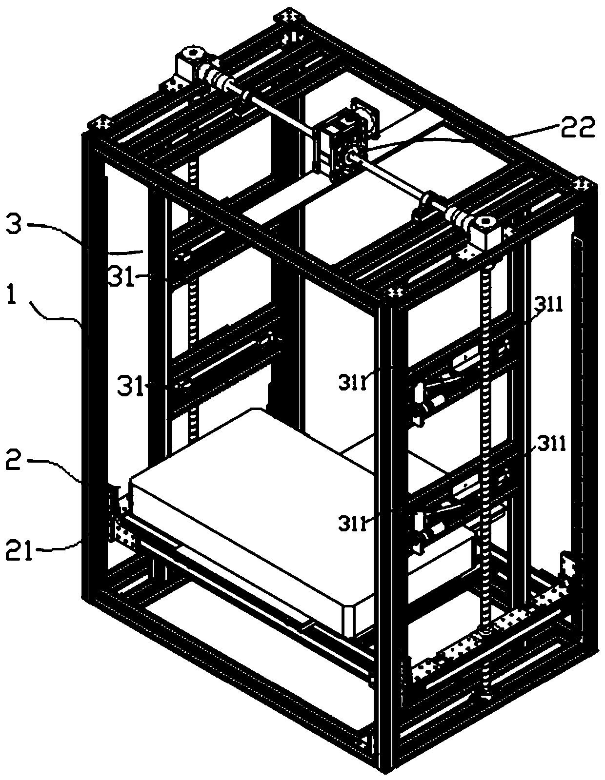
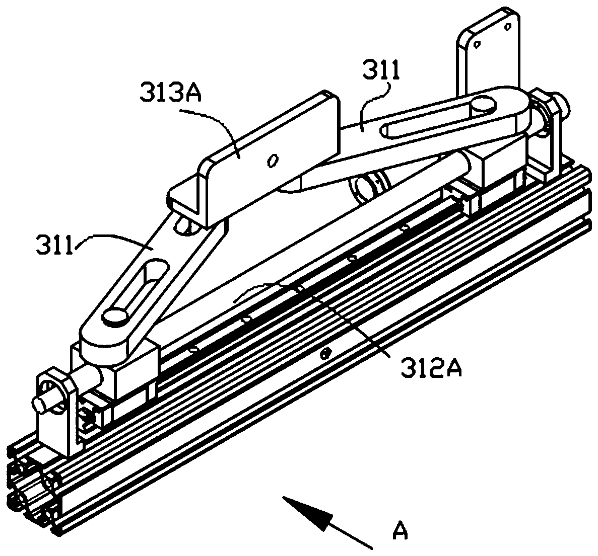
[0072] The movable support 311 is rotatably connected with the base frame 1 , and the movable support 311 can rotate in a plane perpendicular to the lifting direction of the lifting assembly.
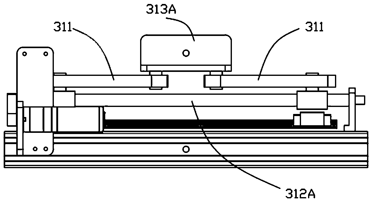
[0073] More specifically, as Figure 1-3 As shown, the support assembly 31 also includes a screw pair 312A and a support shaft 313A;
[0074] The screw pair 312A includes a screw and a nut that cooperate with each other, and the second drive assembly 32 is drivingly connected to the screw;
[0075] The support shaft 313A is fixedly installed on the base frame 1;
[0076] The movable support 311 includes a first chute and a second chute;
[0077] Wherein, the movable supporting member 311 is slidably connected to the nut through the first sliding slot, and the movable supporting member 311 is slidingly connected to the supporting shaft 313A through the second sliding groove.
[0078] During the implementation process, the material is extracted according to the handling information of ...
Embodiment 2
[0084] The movable support 311 is rotatably connected with the base frame 1 , and the movable support 311 can rotate in a plane parallel to the lifting direction.
[0085] More specifically, as Figure 4 As shown, the support assembly 31 also includes a connecting rod 312B and a moving part 313B, and the connecting rod 312B connects the movable supporting part 311 and the moving part 313B through a rotating pair, and the moving part 313B It constitutes a moving pair with the base frame 1; the second driving assembly 32 is drivingly connected with the moving part 313B;
[0086] The movable support 311 is hinged to the base frame 1;
[0087] Wherein, the second driving assembly 32 can drive the moving part 313B to move relative to the base frame 1 , so that the movable supporting part 311 can rotate relative to the base frame 1 .
[0088] During the implementation process, the material is extracted according to the handling information of at least one material;
[0089] Lifti...
Embodiment 3
[0095] The movable support 311 and the base frame 1 form a moving pair, and the movable support 311 can translate relative to the base frame 1 in a plane perpendicular to the lifting direction.
[0096] More specifically, as Figure 5-6 As shown, the support assembly 31 includes a translation assembly 312C, the translation assembly 312C is installed between the movable support 311 and the base frame 1, the translation assembly 312C and the second The second driving assembly 32 is drivingly connected.
[0097] A translation component 312C may be installed between the movable support 311 and the frame, the translation component 312C may be a telescopic component, and the second driving component 32 may be a push cylinder. The translation component 312C may be in the form of a rack and pinion, a sprocket chain, a worm gear or a screw nut, and the second drive unit may be a motor.
[0098] In the unsupported state, the movable support member 311 is at the edge of the lifting cha...
PUM
 Abstract
Description
Claims
Application Information
 - R&D Engineer
- R&D Manager
- IP Professional
- Industry Leading Data Capabilities
- Powerful AI technology
- Patent DNA Extraction
Browse by: Latest US Patents, China's latest patents, Technical Efficacy Thesaurus, Application Domain, Technology Topic, Popular Technical Reports.
© 2024 PatSnap. All rights reserved.Legal|Privacy policy|Modern Slavery Act Transparency Statement|Sitemap|About US| Contact US: help@patsnap.com


