
A fully automatic riveting machine

A riveting press, fully automatic technology, applied in capacitor manufacturing, electrical components, capacitors and other directions, can solve the problems of reduced post-processing work efficiency, unsuitable for industrialized large-scale production, complex assembly machine structure, etc., to avoid low post-processing efficiency. , The device structure is easy to operate, and the site takes up less space.

Inactive Publication Date: 2016-08-31
ZHOUSHAN PUTUO BAOHONG PRECISION MACHINERY
View PDF7 Cites 0 Cited by
  • Summary
  • Abstract
  • Description
  • Claims
  • Application Information

AI Technical Summary

Problems solved by technology

This technical solution is an automated mechanical assembly operation, and the efficiency of manufacturing capacitor cover plates is higher than that of traditional manual operations. Production
The disadvantages of this technical solution are: ① using two rotary conveyors and an intermediate conveyor connecting the two rotary conveyors, which makes the structure of the assembly machine more complicated and takes up a lot of space; The placement direction of the cover plate is strictly limited, and the assembly operation must be completed with the horn facing downward. If the horn is facing upward, the mold must be replaced, so the processing cost will increase additionally; That is, after stamping, the genuine product and the waste product are discharged at the same time, which reduces the efficiency of post-processing

Method used


Image

  • A fully automatic riveting machine
  • A fully automatic riveting machine
  • A fully automatic riveting machine

Examples


Embodiment Construction

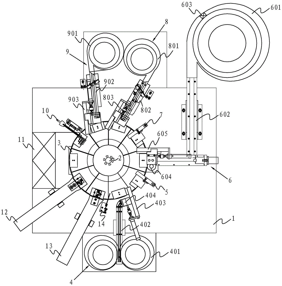
[0030] Such as figure 1 As shown, a full-automatic riveting press includes a frame, a transmission transmission mechanism arranged on the frame, and a rotary conveying device driven by the transmission transmission mechanism. The rotary conveying device includes a worktable 1, and the center of the worktable 1 is arranged There is a vertical shaft 2 coaxially connected with the transmission transmission mechanism. The outer periphery of the worktable 1 is composed of ten mold tables 3 that rotate around the vertical shaft 2. Each mold table 3 is equipped with a capacitor cover mold. There are two holes on the cover mold. A hole that fits the size of the pin rivet; the transmission speed change mechanism can be adjusted arbitrarily according to actual needs, and its transmission mode can be one or more of discs, crawlers, endless plate chains, and annular tracks.

[0031] The pin rivet upper mold device 4, the pin rivet detection device 5, the lid upper mold device 6, the lid d...


PUM


Abstract

The invention discloses a full-automatic riveting machine. The full-automatic riveting machine comprises a machine frame, a transmission speed change mechanism and a rotation conveying device, wherein the transmission speed change mechanism is arranged on the machine frame; the rotation conveying device is driven by the transmission speed change mechanism; the rotation conveying device comprises a workbench; the center of the workbench is provided with a vertical shaft coaxially connected with the transmission speed change mechanism; the periphery of the workbench is composed of ten die tables rotating around the vertical shaft; each die table is provided with a capacitor cover board die; a pin rivet feed device, a pin rivet detection device, a cover feed device, a cover detection device, a first horn feed device, a second horn feed device, a horn detection device, a stamping device, a finished product discharge device and a defective product discharge device all of which work in cooperation with the die tables are installed on the walking path of the workbench in sequence. The full-automatic riveting machine is simple in structure, easy to operate and small in occupied floor space, the die does not need to be replaced, and machining cost is lowered; the unique design of double guide rails, a cover blowing assembly and the like is adopted, the pass percent of products is ensured, and the machining efficiency of riveting is improved.

Description

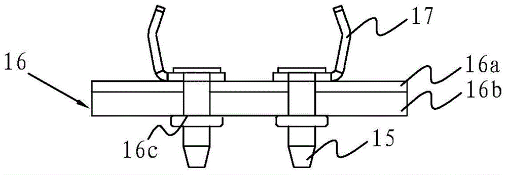
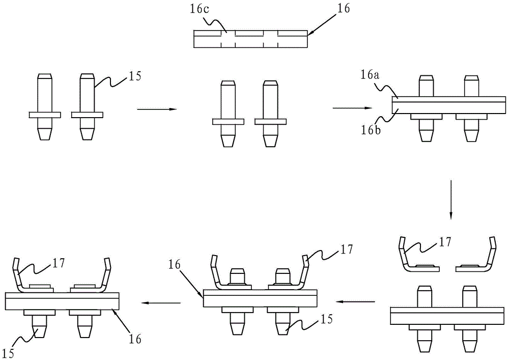
technical field [0001] The invention relates to the technical field of special equipment for manufacturing capacitors, in particular to a fully automatic riveting press, which is mainly used for the assembly of capacitor cover plates, especially for the specific assembly of welding-free capacitor cover plates. Background technique [0002] The capacitor referred to in the present invention is an electrolytic capacitor, which generally consists of a casing, a core package and a cover plate. Among them, the cover plate is a cover composed of a layer of insulating board and a layer of gasket, and a horn and a pin rivet are stamped on both sides of the cover; , A corner-shaped component is formed on one side. [0003] Assembling the capacitor cover plate, the traditional assembly method is to insert the pin rivets into the two holes on the cover from one side of the insulating plate, and then put the horns on the pins on the other side of the cover, and finally place them in th...

Claims


Application Information

Patent Timeline
Patent Type & Authority Patents(China)
IPC IPC(8): H01G13/00
Inventor 胡冶红林欣久
Owner ZHOUSHAN PUTUO BAOHONG PRECISION MACHINERY
Learn More