Stone floor system and construction method thereof

A floor and stone technology, applied in the direction of floors, buildings, building structures, etc., can solve the problems affecting the overall flatness of the stone floor and the low stone floor, so as to reduce the settlement difference, improve the flatness, and reduce the height difference. Effect

Active Publication Date: 2019-10-25
深圳市新雅建设工程有限公司
View PDF8 Cites 3 Cited by
  • Summary
  • Abstract
  • Description
  • Claims
  • Application Information

AI Technical Summary

Problems solved by technology

[0004] According to the above method, the stone floor can be laid, but when the stone floor is laid, even if the staff spread the mortar relatively flat and level the upper surface of the stone floor, the follow-up will be affected by the weight of the stone and the dryness and wetness of the cement slurry. It is always inevitable that some stone floors will be higher or lower than the surrounding position after curing, which will affect the overall flatness of the stone floor, so a new solution needs to be proposed to solve this problem

Method used


Image

  • Stone floor system and construction method thereof
  • Stone floor system and construction method thereof
  • Stone floor system and construction method thereof

Examples


Embodiment 1

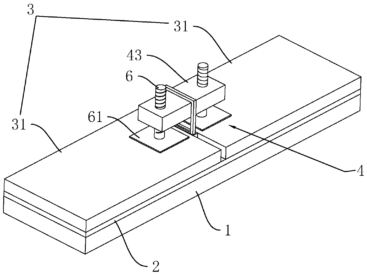
[0038] Stone flooring system, see figure 1 , including a sand and gravel leveling layer 1, a cement slurry layer 2 and a floor layer 3 arranged on the base floor in sequence from bottom to top, the sand and gravel leveling layer 1 is made of coarse sand, cement and water, and it is paved on the base ground It is used for leveling; the grout layer 2 is made of cement and water, which is used for bonding the floor layer 3; the floor layer 3 includes a plurality of evenly laid floors 31 .

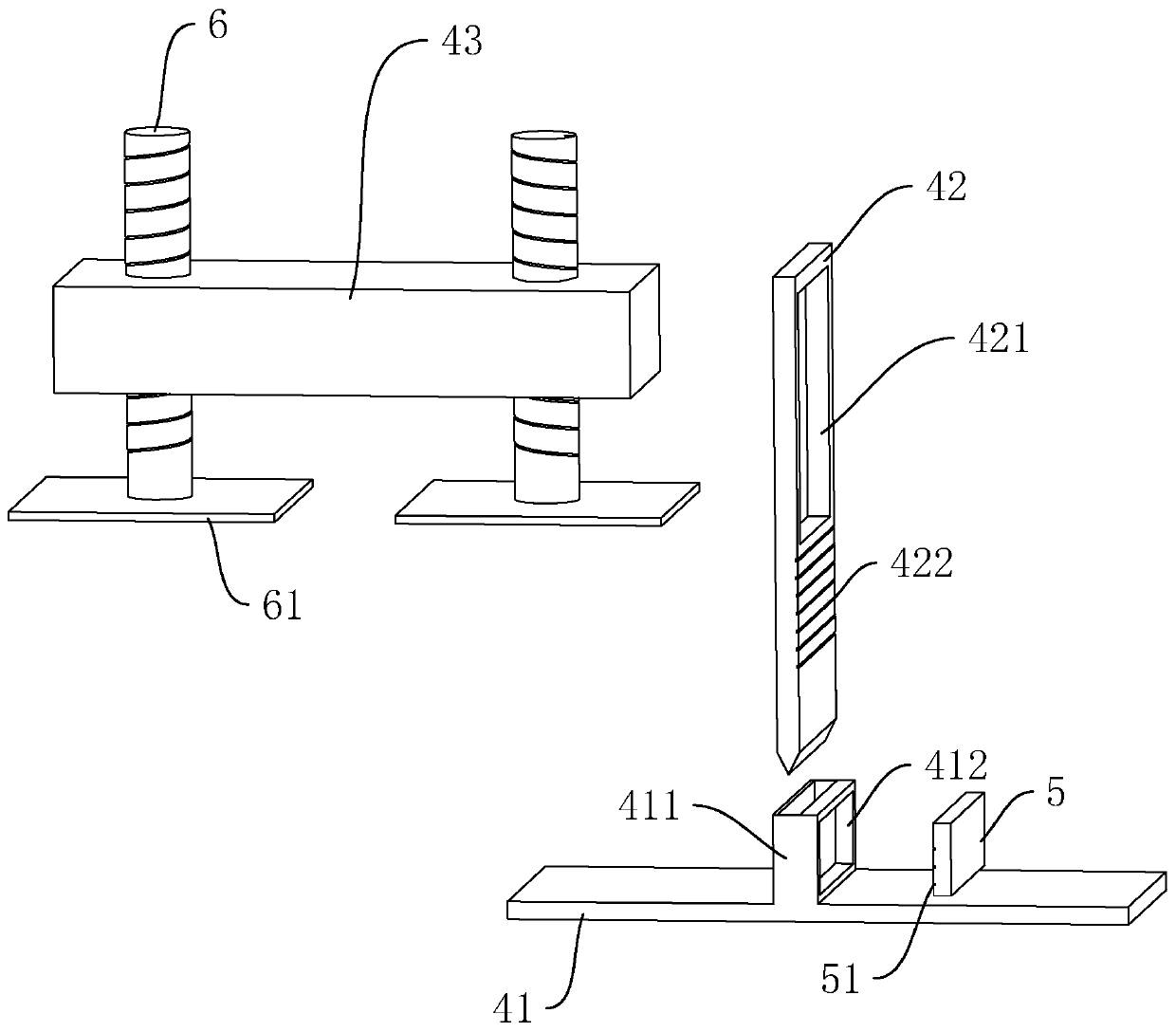
[0039] refer to figure 1 and figure 2 , in order to improve the flatness of the floor layer 3, a leveling mechanism 4 is provided for leveling its plurality of floors 31 during its laying stage. The leveling mechanism 4 includes a lower support plate 41 , an abutment column 42 vertically penetrating the lower support plate 41 , and an upper pressing plate 43 connected to the abutment column 42 .

[0040] In the state of use, both ends of the lower supporting plate 41 are placed horizontall...

Embodiment 2

[0045] Stone floor system, see figure 2 The difference from Embodiment 1 is that the abutment column 42 is vertically slidably connected to the lower bearing plate 41. The reason for this arrangement is that the lower end of the abutment column 42 protrudes from the lower plate of the lower bearing plate 41 when it is in use. surface, and the installation of the lower bearing plate 41 is preferably inserted under the floor 31 after laying a floor 31, which causes the lower part of the abutment column 42 to easily draw a groove on the cement slurry layer 2 and sand and gravel leveling layer 1, increasing repair Step: After the abutment column 42 is set to vertically slide and connect to the lower bearing plate 41, it can be detachably connected to the lower bearing plate 41, and then the abutment column 42 can be installed after the lower bearing plate 41 is installed to avoid scratching. out of the ditch.

[0046] The abutting column 42 is plate-shaped; in order to still be ...

Embodiment 3

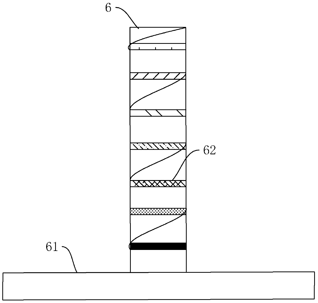
[0050] Stone floor system, see figure 2 , The difference with Embodiment 1 or 2 is that: the two ends of the upper pressing plate 43 protruding from the through hole 421 are vertically pierced with the fine-tuning screw 6 respectively, and the fine-tuning screw 6 and the upper pressing plate 43 are threadedly connected.

[0051] When in use, the staff first passes the upper pressing plate 43 through the through hole 421, and then turns the fine-tuning screw 6 to make it abut against the floor 31, so that the adjacent floor 31 can be kept flat; at the same time, the staff can also turn the fine-tuning screw 6. Fine-tuning the amount of pushing on the floor 31, that is, fine-tuning the flatness of the floor 31, so that the floor 31 can be laid more evenly.

[0052] The upper plate 43 and the fine-tuning screw 6 are preferably made of metal, because it is necessary to reduce the interference of deformation on the use effect; the lower bearing plate 41 and the abutting column 42 ...


PUM


Abstract

The invention discloses a stone floor system and a construction method thereof, relates to the field of building decoration, and aims to solve the problem of higher influence on stone floor pavement flatness by self weight and dry humidity of cement mortar in the prior art. The stone floor system is characterized by comprising a gravel leveling layer, a cement pulp layer and a floor layer; and thefloor layer comprises multiple floors. The stone floor system further comprises a leveling mechanism; the leveling mechanism comprises a lower bearing plate, butting columns and upper pressing plates; the two ends of the lower bearing plate are in butt joint with the lower parts of two adjacent floors at the same time; the butting columns are positioned between two adjacent floors; the lower endsof the butting columns are in butt joint with a base layer ground, and the upper ends extend out planes of upper surfaces of the floors and are transversely provided with through holes; the upper pressing plates penetrate through the through holes; and the two ends are in butt joint with the upper surfaces of two adjacent floors. The stone floor system and the construction method thereof can reduce the troubles caused by self weight of stones and the dry humidity of the cement mortar, and improve the overall flatness of the floors.

Description

technical field [0001] The invention relates to the field of building decoration, more specifically, it relates to a stone floor system and a construction method thereof. Background technique [0002] For ground decoration, especially for interior decoration, stone floors (such as marble tiles) are currently chosen to be laid on the foundation ground to make the ground more tidy and beautiful. [0003] The existing stone floor laying methods are as follows: 1. Cleaning the base floor; 2. Calibrating the height and opening the line; 3. Soaking the board in water; 4. Spreading cement mortar; 5. Installing the standard board; 6. Paving the stone floor; 7. Filling joints; 8. Cleaning. [0004] According to the above method, the stone floor can be laid, but when the stone floor is laid, even if the staff spread the mortar relatively flat and level the upper surface of the stone floor, the follow-up will be affected by the weight of the stone and the dryness and wetness of the ce...

Claims


Application Information

Patent Timeline
Patent Type & Authority Applications(China)
IPC IPC(8): E04F15/08E04F21/22
CPCE04F15/08E04F21/22
Inventor 甘贇甘锦添戴小兰陈嘉玲甘庆新
Owner 深圳市新雅建设工程有限公司
Why Eureka
Try Eureka