
A diaphragm compressor cylinder head cooling structure

A technology of diaphragm compressor and cooling structure, applied in the field of compressors, can solve the problems of air separation pressure and saturated vapor pressure rise, pressure fluctuation of hydraulic system, etc.

Active Publication Date: 2020-06-26
XI AN JIAOTONG UNIV
View PDF6 Cites 0 Cited by
  • Summary
  • Abstract
  • Description
  • Claims
  • Application Information

AI Technical Summary

Problems solved by technology

An increase in the temperature of the hydraulic oil will also lead to an increase in the air separation pressure and saturated vapor pressure in the hydraulic oil, making cavitation more likely to occur and causing pressure fluctuations in the hydraulic system. This application provides a diaphragm compressor cylinder Cover cooling structure

Method used


Image

  • A diaphragm compressor cylinder head cooling structure
  • A diaphragm compressor cylinder head cooling structure
  • A diaphragm compressor cylinder head cooling structure

Examples


Embodiment Construction

[0021] Hereinafter, specific embodiments of the present application will be described in detail with reference to the accompanying drawings. According to these detailed descriptions, those skilled in the art can clearly understand the present application and can implement the present application. Without departing from the principle of the present application, the features in different embodiments can be combined to obtain new implementations, or some features in certain embodiments can be replaced to obtain other preferred implementations.

[0022] Most of the existing cooling schemes are to build cooling water channels inside the cylinder head, and pass water or oil for cooling. The high-temperature area of ​​the diaphragm compressor is mainly concentrated near the exhaust valve in the central area, and there is always high-temperature exhaust air passing through, and the heat flux density is also relatively high. However, the traditional cooling method uses the cooling water...


PUM


Abstract

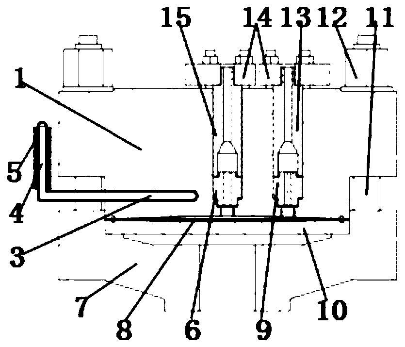
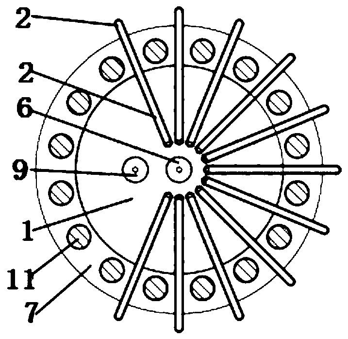
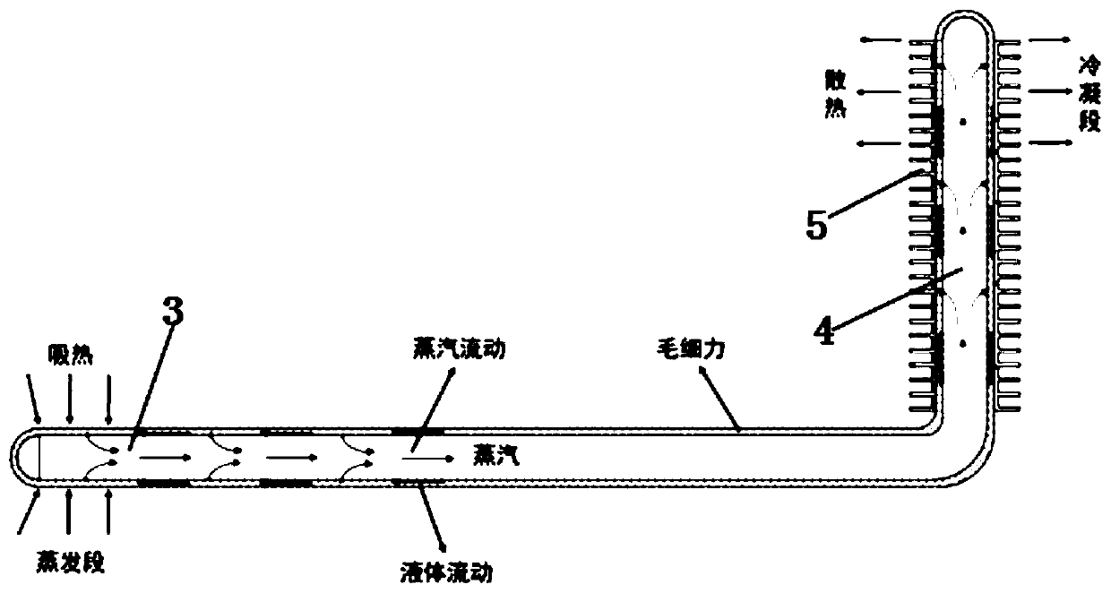
The invention belongs to the technical field of compressors, and particularly relates to a cooling structure of a cylinder head of a diaphragm compressor. A diaphragm compressor is large in pressure ratio generally, a cylinder head is thick, the exhaust temperature is high, and compression heat in a diaphragm cavity cannot be easily guided out timely through heat exchange of the surface of the cylinder head. Therefore, the overall temperature of the cylinder head is high, so that heat stress of the cylinder head cannot be neglected, a pressure valve cover and an exhaust flange bolt are causedto be loosened, and the operation safety of a system is endangered. The cooling structure of the cylinder head of the diaphragm compressor comprises the cylinder head, wherein a heat pipe is arrangedon the cylinder head, one end of the heat pipe is arranged in the cylinder head, and the other end of the heat pipe is free. The high-heat-flux heat pipe is adopted for heat dissipation, a heat pipe evaporation section is close to a central high-temperature area as far as possible so as to guide out heat of the central high-temperature area, and the temperature of the cylinder head and the exhausttemperature are reduced.

Description

technical field [0001] The application belongs to the technical field of compressors, and in particular relates to a cooling structure for a cylinder head of a diaphragm compressor. Background technique [0002] Diaphragm compressor is a positive displacement compressor. Because of its good sealing performance, wide pressure range and large compression ratio, it is widely used in petrochemical fields such as hydrogenation stations to compress and transport various high-purity gases, Precious and rare gases, toxic and harmful gases and corrosive gases. In the diaphragm compressor, the piston pushes the working oil in the cylinder oil chamber, and then pushes the diaphragm to reciprocate in the diaphragm chamber to change the working volume of the air chamber, and achieve no leakage with the cooperation of the suction and exhaust valves periodic work process. [0003] Because the pressure ratio of the diaphragm compressor is generally large, especially the cylinder head of t...

Claims


Application Information

Patent Timeline
Patent Type & Authority Patents(China)
IPC IPC(8): F04B39/06F04B39/12F04B45/04
CPCF04B39/06F04B39/125F04B45/04
Inventor 贾晓晗任省栋汪婷彭学院
Owner XI AN JIAOTONG UNIV
Learn More