Time consistency control method oriented to cooperative guidance simulation system

A simulation system and control method technology, which is applied to projectiles, self-propelled missiles, offensive equipment, etc., can solve the problems of simple time consistency control method, no specific time consistency control, and no aircraft, etc., to achieve the improvement cycle The effect of state consistency, improving initial state consistency, and improving calculation accuracy

Active Publication Date: 2019-10-25
BEIJING RES INST OF MECHANICAL & ELECTRICAL TECH
View PDF5 Cites 0 Cited by
  • Summary
  • Abstract
  • Description
  • Claims
  • Application Information

AI Technical Summary

Problems solved by technology

[0003] At present, there is no mature time-consistency control method for cooperative guidance hardware-in-the-loop simulation test, the reasons are: (1) In some hardware-in-the-loop simulation environments, only the simulation environment is taken as a whole, and the interaction between subsystems in the simulation environment is not considered. time difference, or consider the time difference between subsystems, but think that the punctuality accuracy of the subsystem is within the allowable error, so no specific time consistency control is performed; (2) Even if some semi-physical simulation environments consider the time difference between subsystems However, since there is no need for collaborative interaction between aircraft, the time difference margin between subsystems in the existing hardware-in-the-loop simulation en

Method used


Image

  • Time consistency control method oriented to cooperative guidance simulation system
  • Time consistency control method oriented to cooperative guidance simulation system
  • Time consistency control method oriented to cooperative guidance simulation system

Examples


Embodiment Construction

[0049] The present invention will be described in detail below in conjunction with the accompanying drawings and embodiments.

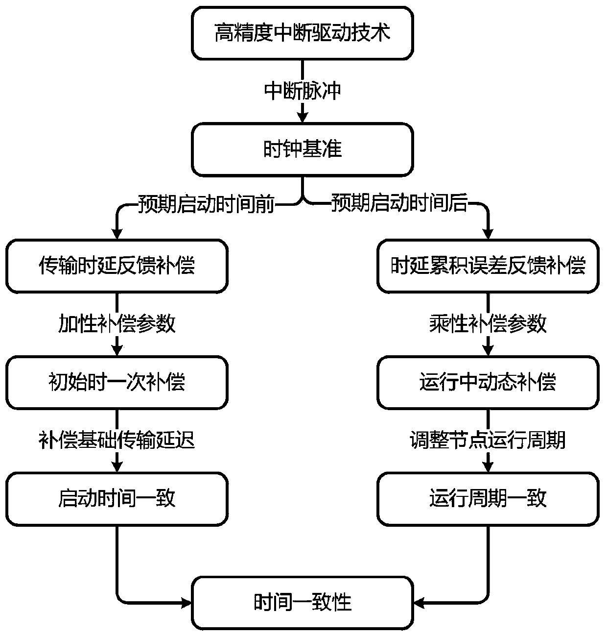
[0050] The present invention proposes a time consistency control method for a cooperative guidance simulation system, which can control the time difference on each node in the simulation system to the nanosecond level, and provide more accurate simulation clock and accurate timing for the cooperative guidance semi-physical simulation control. Such as figure 1 As shown, the time consistency control method includes the following three closely related sub-technologies:

[0051] Sub-technology 1. During the operation of the simulation system, high-precision interrupt driving is performed according to the expected startup time and operating cycle

[0052] High-precision interrupt-driven technology utilizes FPGA programming technology and software drivers to enable the multi-aircraft cooperative guidance simulation system to have the ability to respond to...


PUM


Abstract

The invention provides a time consistency control method oriented to a cooperative guidance simulation system. On the basis of the existing time system, the technologies of high-precision interrupt drive, data transmission delay feedback compensation, and delay accumulative error feedback compensation are added. The time consistency control method comprises the following steps: at first, the high-precision interrupt drive technology is utilized to introduce a high-precision clock signal and an interrupt pulse into the cooperative guidance simulation system to drive nodes in the system to operate synchronously; then, unexpected delay of a command in an optical fiber transmission network is taken into consideration, and data transmission delay feedback compensation is introduced to realize one-time compensation of transmission delay and fluctuation; and finally, aiming at the residence time error problem, dynamic delay accumulative error feedback compensation is put forward, and intervalmeasurement and multiframe compensation are utilized to finish the state elastic propulsion during the operating process of the system. With adoption of the time consistency control method, the existing cooperative guidance simulation system is enhanced, nanosecond-grade time control precision between the nodes of the simulation system can be realized, and the problem about time consistency control in the cooperative guidance simulation system is solved.

Description

technical field [0001] The invention belongs to the technical field of hardware-in-the-loop simulation, and in particular relates to a time consistency control method for a cooperative guidance simulation system. Background technique [0002] The multi-aircraft cooperative guidance simulation system is composed of test equipment, simulation models, and physical effect simulation equipment distributed in different test sites. It has the characteristics of many test nodes and a wide deployment range. In order to truly reproduce the logical timing of the combat process, it is necessary to control the time consistency of the nodes in the system. The time consistency control equipment is used to provide high-precision time information for the nodes. At the same time, the time delay error is calculated by monitoring the time stamp of the transmitted information in the system. The transmission delay and delay accumulation error are dynamically calibrated and compensated, so as to e...

Claims


Application Information

Patent Timeline
IPC IPC(8): F42B15/01
CPCF42B15/01
Inventor 韩健李景李平郭卓峰史航
Owner BEIJING RES INST OF MECHANICAL & ELECTRICAL TECH
Why Eureka
Try Eureka