Wall verticality detecting device for building supervision

A detection device and verticality technology, which is applied in the field of wall verticality detection devices for construction supervision, can solve problems such as troublesome use and inability to measure wall verticality

Inactive Publication Date: 2019-10-25
深圳市华建工程项目管理有限公司
View PDF14 Cites 1 Cited by
  • Summary
  • Abstract
  • Description
  • Claims
  • Application Information

AI Technical Summary

Problems solved by technology

A wall verticality detector used for real estate evaluation in the above-mentioned patents has the following disadvantages: when detecting, the device needs to be hung at a high place, which is troublesome to use, and at the same time, the device can only detect the verticality of one wall. Unable to measure the verticality of an entire wall

Method used


Image

  • Wall verticality detecting device for building supervision
  • Wall verticality detecting device for building supervision
  • Wall verticality detecting device for building supervision

Examples


Embodiment 1

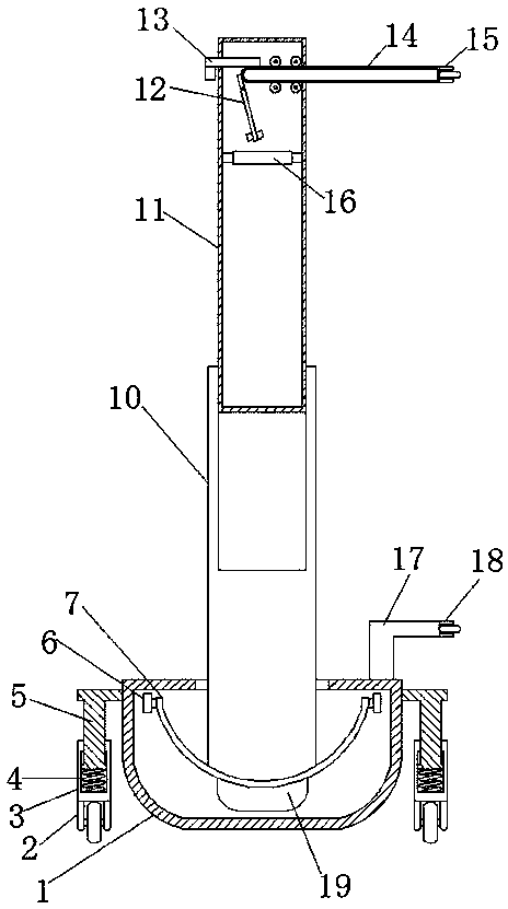
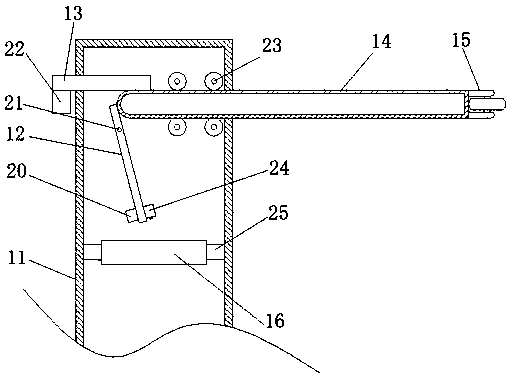
[0030] refer to Figure 1-5 , a wall verticality detection device for construction supervision, comprising a main body 1, a first cavity is provided inside the main body 1, a first rotating ring 6 is connected to the main body 1 in rotation between the inner walls of both sides of the first cavity, the second The inner wall of a rotating ring 6 is rotatably connected with a second rotating ring 7, the middle top of the second rotating ring 7 is welded with a fixed sleeve 10, the top of the fixed sleeve 10 is provided with a first moving rod 11, and one side of the first moving rod 11 A second moving rod 14 is provided, and one end of the second moving rod 14 is welded with a second roller 15, and the inside of the first moving rod 11 is provided with a second cavity, and the second moving rod 14 extends to the inside of the second cavity, The first moving rod 11 is welded with a fixed shaft 21 inside the second cavity, the middle part of the fixed shaft 21 is rotatably connect...

Embodiment 2

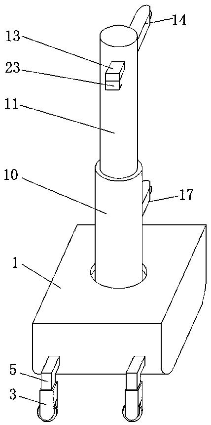
[0041] refer to Image 6 , a wall verticality detection device for construction supervision. Compared with Embodiment 1, in this embodiment, in order to increase the stability of the device, the main body 1 is provided with a through hole at the top inner wall of the first cavity, and the fixed sleeve 10 is in the through hole. The hole extends to the outside of the main body 1, the main body 1 is provided with four first magnets 8 at the through hole, and the outer wall of the fixed sleeve 10 is provided with four second magnets 9, the first magnet 8 and the second magnet 9 are close to each other The magnetic poles on one side are opposite, and when the device is moving, the repulsive force between the first magnet 8 and the second magnet 9 can prevent the fixed sleeve 10 from excessively swinging, so that the device can be stabilized faster.

[0042] During use, the device is placed on the ground, the third roller 18 is pressed against the detection wall, and the device is ...


PUM


Abstract

The invention, which belongs to the technical field of construction equipment, in particular relates to a wall verticality detecting device for building supervision, thereby solving problems that thedrop hammer needs to be suspended at a high altitude and thus is used inconveniently and the device only detects the verticality of one wall but can not measure the verticality of the whole wall. Thedetecting device comprises a main body; and a first cavity is formed in the main body. A first rotating ring is connected between the inner walls of the two sides of the first cavity of the main bodyin a rotating manner; a second rotating ring is connected at the inner wall of the first rotating ring in a rotating manner; and a fixed sleeve is welded to the top of the middle part of the second rotating ring. According to the invention, a second roller changes with changing of the inclination of the wall to drive a second moving rod to move and thus a rotating rod rotates; a laser emitter arranged at the bottom end of the rotating rod rotates and the moving distance of the second roller is extended by the rotating rod; and laser emitted by the laser emitter is irradiated on a photographicfilm to form a curve. The larger the curvature of the curve, the larger the inclination of the wall.

Description

technical field [0001] The invention relates to the technical field of construction equipment, in particular to a wall verticality detection device for construction supervision. Background technique [0002] After the construction is completed, the verticality of the wall is one of the important indicators of the construction quality. The inclined wall will make the wall easy to fall after being stressed, and there are potential safety hazards. Therefore, the verticality of the wall will be tested after the construction is completed. , to judge whether the project is qualified. [0003] After retrieval, the Chinese patent application number is 201721830948.5, which discloses a wall verticality detector for real estate evaluation, including a suspension device, which includes a hanging rope and a hanging rope connected to one end of the hanging rope. hammer, the bottom of the suspension device is slidably connected with a stabilizing device, and the stabilizing device includ...

Claims


Application Information

Patent Timeline
Patent Type & Authority Applications(China)
IPC IPC(8): G01C15/12
CPCG01C15/12
Inventor 王焱金波李雯张政李子玉丁志雄
Owner 深圳市华建工程项目管理有限公司
Why Eureka
Try Eureka