Double-layer piston type tensile and compression tensionmeter

A technology of piston type and tension gauge, applied in the field of dynamometer, can solve the problems that the press is difficult to clamp, bulky, and the tension gauge can only exert force in one direction, and achieve the effect of small diameter and convenient installation and use

Pending Publication Date: 2019-10-25
SHANDONG UNIV OF SCI & TECH
View PDF0 Cites 1 Cited by
  • Summary
  • Abstract
  • Description
  • Claims
  • Application Information

AI Technical Summary

Problems solved by technology

The measuring range of the existing piston pressure gauge is related to the pressure area of ​​the piston, so if the measuring range is large, the diameter and volume will be large, very heavy, and inconvenient to install and use
[0003] Existing piston-type tension gauges design the piston of the piston-type pressure gauge as a hollow type, and install a pull rod from the center hole to protrude from the bottom of the cylinder to become a tension gauge. For example, the anchor rod tension gauge is in this form; due to structural reasons, This kind of tension gauge can only apply force in one direction, and cannot apply tension in two directions like the general-purpose tension gauge; therefore, most tension gauges are strain gauges, which do not reflect the advantages of the piston type; ring, the press is often difficult to clamp, especially the large-tonnage tension gauge cannot be easily calibrated on the press

Method used


Image

  • Double-layer piston type tensile and compression tensionmeter
  • Double-layer piston type tensile and compression tensionmeter

Examples


Embodiment Construction

[0015] Embodiments are further described below according to the accompanying drawings.

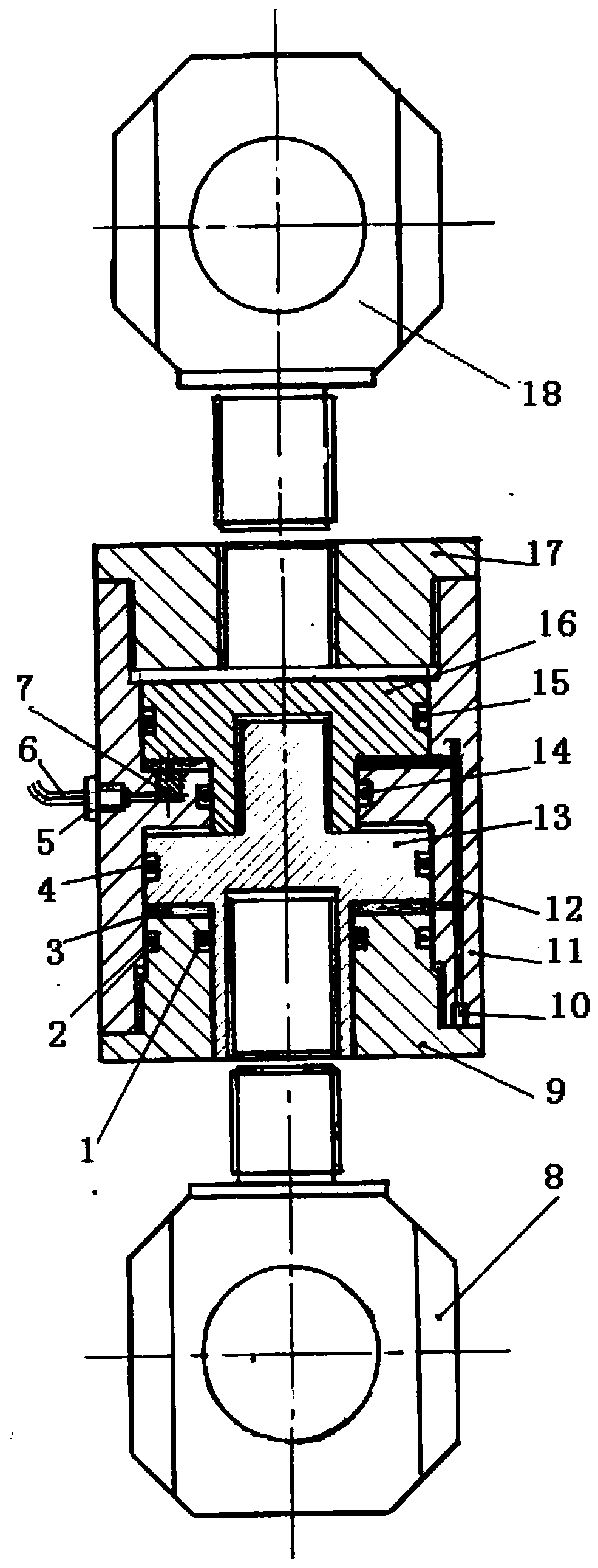
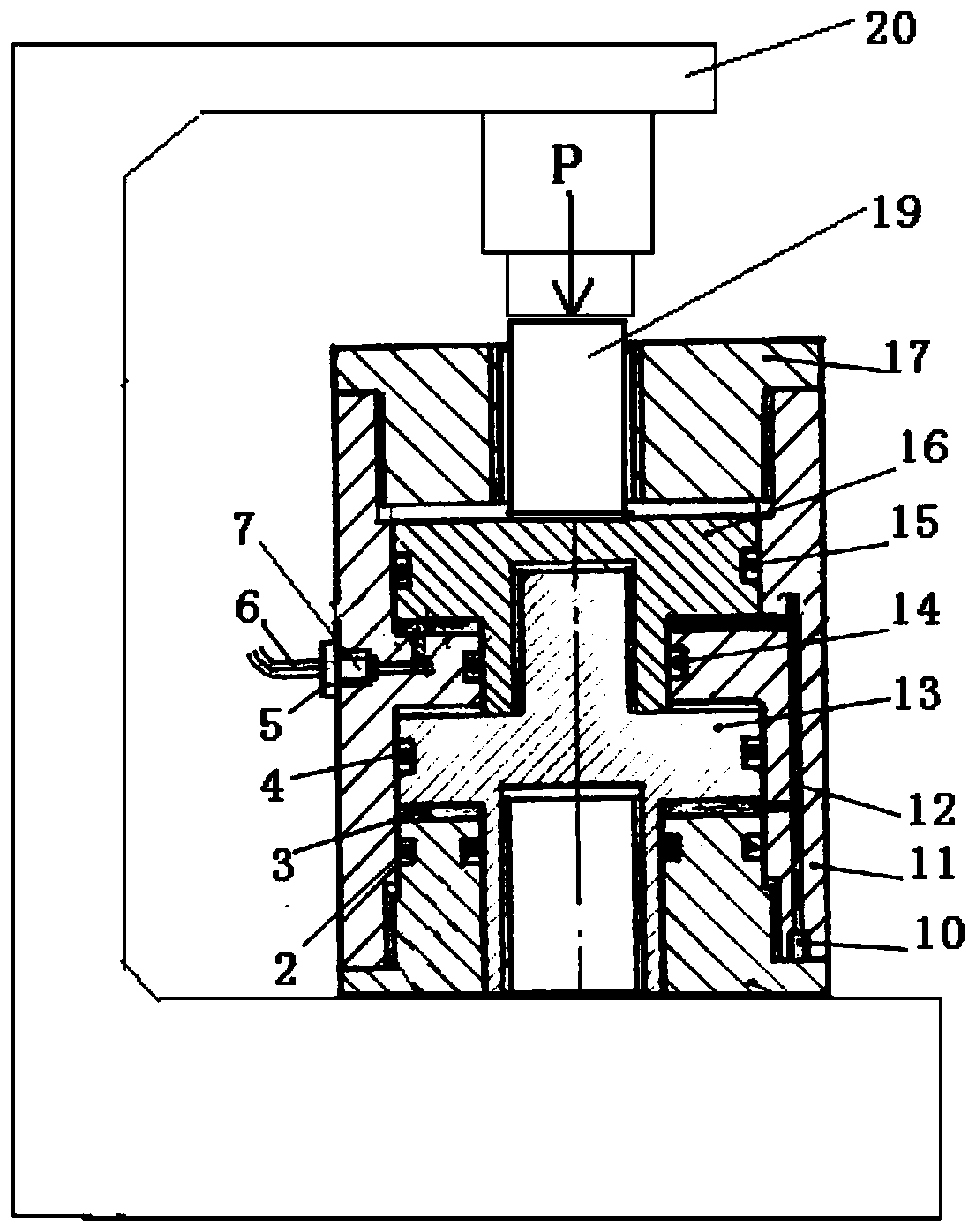
[0016] Such as figure 1 As shown, a double-layer piston type pull-compression dual-purpose tension meter consists of a cylinder body (including cylinder barrel 11 and cylinder bottom member 9), piston (including upper piston 16 and lower piston 13), grease 3, top cover 17 and The liquid pressure sensor 7 is formed; wherein, the cylinder bottom of the cylinder body is an independent part, that is, the cylinder body is composed of a cylinder barrel 11 and a cylinder bottom part 9, and the cylinder bottom part 9 is provided with a central round hole, and the cylinder bottom part 9 passes through Threaded on the lower opening of the cylinder barrel 11; the cylinder body is provided with a gap, and the gap is provided with a central round hole, so that the cylinder cavity forms two cylinder cavities connected up and down; the piston is two connected up and down. The T-shaped piston of solid st...


PUM


Abstract

The invention discloses a double-layer piston type tensile and compression tensionmeter which is composed of a cylinder body, a piston, grease, a top cover and a fluid pressure sensor. The tensionmeter is characterized in that the cylinder is composed of a cylinder and a cylinder bottom member; the cylinder body is internally provided with an interval which forms cylinder cavities communicated with each other up and down; the T-shaped piston is of an upper-lower connecting structure; the cylinder is provided with a sealed oil duct so that upper and down annular pressure cavities are communicated with each other; a protruded portion and top cover of the lower piston are provided with central threaded holes respectively, and can be connected with upper pulling force rings in a threaded way via the central threaded holes, thus, serve as the tensionmeter; the fluid pressure sensor generates an electric signal and sends the electric signal to a data collector via a signal line, and a pulling force value is calculated; and after that a movable bearing cylinder is mounted in the central threaded hole of the top cover, the tensionmeter can be directly mounted between a pressure object anda pressed object to measure the pressure value.

Description

technical field [0001] This invention relates to force gauges. Background technique [0002] The technology related to the present invention is the existing piston pressure gauge and tension gauge. The structure of the existing piston pressure gauge is composed of an oil cylinder and a piston. There is a space between the bottom surface of the piston and the bottom of the oil cylinder. There is a screw hole communicating with the space on the side of the oil cylinder. The space is filled with grease with a temperature below -20°C. The hole is connected with a liquid pressure sensor, which converts the pressure applied to the piston into an electrical signal output. When leaving the factory or before use, it is necessary to calibrate on the press to find out the relationship curve between the electrical signal value and the corresponding pressure. The output is an electrical signal. Before use, it needs to be calibrated to establish the relationship between the electrical si...

Claims


Application Information

Patent Timeline
Patent Type & Authority Applications(China)
IPC IPC(8): G01L1/02G01L25/00
CPCG01L1/02G01L25/00
Inventor 栾兆群胡建明王海永张涛
Owner SHANDONG UNIV OF SCI & TECH
Why Eureka
Try Eureka