Display panel and display device

A display panel and display area technology, applied in the direction of electrical components, electrical solid devices, circuits, etc., can solve problems such as short circuit of wiring, achieve the effect of improving stability and improving product mass production yield

Active Publication Date: 2019-10-25
YUNGU GUAN TECH CO LTD
View PDF5 Cites 3 Cited by
  • Summary
  • Abstract
  • Description
  • Claims
  • Application Information

AI Technical Summary

Problems solved by technology

[0005] The present invention provides a display panel and a display device to solve the problem of short circuit caused by other metal residues above the fan-out area, improve the stability of the electrical connection of the display panel, and improve the mass production yield of products

Method used


Image

  • Display panel and display device
  • Display panel and display device
  • Display panel and display device

Examples


Embodiment 1

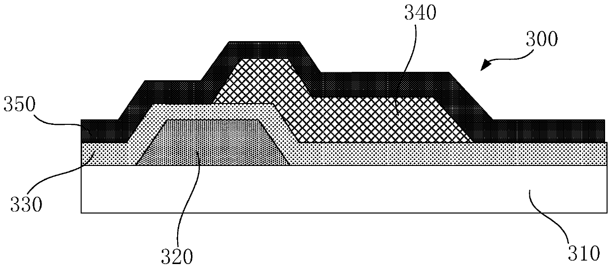
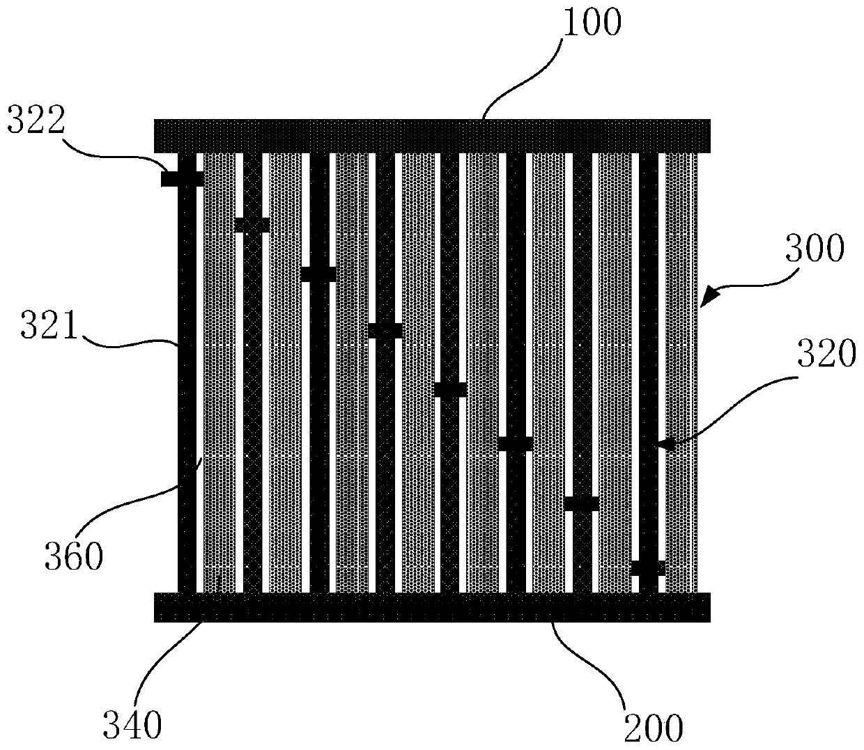
[0048] This embodiment provides a display panel, which includes a display area 100, a driver 200, and a fan-out area 300. among them, figure 2 It is a schematic structural diagram of an implementation manner of a sector area in a display panel in an embodiment of the present invention. Such as figure 2 As shown, the fan-out area 300 is connected to the display area 100 and the driver 200. When specifically arranged, the fan-out area 300 includes a substrate 310, a plurality of first metal wires 320, an insulating layer 330, a plurality of second metal wires 340, and interlayers. The dielectric layer 350, wherein: a plurality of first metal wires 320 are spaced apart and arranged in parallel above the substrate 310, an insulating layer 330 covers the plurality of first metal wires 320; a plurality of second metal wires 340 spaced apart and arranged in parallel on the insulating layer 330 Above, each second metal line 340 is located between two adjacent first metal lines 320, t...

Embodiment 2

[0077] This embodiment provides a display device. The display device may be an OLED display device and any product or component with a display function such as a TV, digital camera, mobile phone, tablet computer, smart watch, e-book, navigator, etc., including the OLED display device. .

[0078] The display device includes: the display panel in the first embodiment. Among them, the structure, function and implementation of the display panel can be the same as in the first embodiment, and will not be repeated here.

[0079] The display device of this embodiment includes a display panel. In the display panel, the first metal wire and the second metal wire are arranged in different layers and alternately. Because a part of the second metal wire overlaps the insulation directly above the first metal wire On the layer, an interlayer gap is formed between the other part of the second metal line and the first metal line, so that the corresponding interlayer dielectric layer forms a depre...


PUM


Abstract

The invention provides a display panel and a display device. The display panel comprises a display area, a driver and a fan-out area connecting the display area and the driver, wherein the fan-out area includes a substrate, a plurality of first metal wires, an insulating layer, a plurality of second metal wires and an interlayer dielectric layer; the plurality of first metal wires are arranged onthe substrate in parallel at intervals; the insulating layer covers the plurality of first metal wires; the plurality of second metal wires are arranged on the insulating layer in parallel at intervals, each second metal wire is positioned between two adjacent first metal wires, and the interlayer dielectric layer covers the plurality of second metal wires. In the adjacent first metal wire and thesecond metal wire, one part of the second metal wire is overlapped on the insulating layer right above the first metal wire, the other parts of the second metal wire form a slit with the first metalwire when the fan-out area becomes narrow, the overlapping part forms a bulge to prevent the slit from connecting the display area and the driver, thereby preventing the residue of other metal layersfrom resulting in a short circuit between the display area and the driver.

Description

Technical field [0001] The invention relates to a display panel and a display device, belonging to the technical field of organic light emitting display. Background technique [0002] In the field of organic light-emitting display technology, organic light-emitting diodes (Organic Light-EmittingDiode, abbreviated as: OLED) have excellent advantages such as low power consumption, high brightness, self-luminescence, high color saturation, wide viewing angle, thin thickness, and flexibility. Performance, so it is widely used in display devices such as terminal equipment and wearable equipment. [0003] With the development of display technology, the public has higher and higher requirements for display screens. Users are no longer satisfied with the viewing effect of existing display devices. They have put forward higher requirements for visual experience. The narrowing of the display screen has become an inevitable development. Trends, especially when organic light-emitting diodes a...

Claims


Application Information

Patent Timeline
Patent Type & Authority Applications(China)
IPC IPC(8): H01L27/32
CPCH10K59/124H10K59/1315
Inventor 刘勋
Owner YUNGU GUAN TECH CO LTD
Why Eureka
Try Eureka