Eureka AIR delivers breakthrough ideas for toughest innovation challenges, trusted by R&D personnel around the world.

Active antenna unit and antenna unit for base stations

A technology of active antenna and antenna unit, which is applied in the direction of antenna, antenna parts, radiation unit cover, etc., can solve the problems of signal leakage and interference, and achieve the effect of ensuring sealing, avoiding interference and avoiding signal leakage

Pending Publication Date: 2019-10-25
ANHUI TATFOOK TECH CO LTD
View PDF0 Cites 0 Cited by
  • Summary
  • Abstract
  • Description
  • Claims
  • Application Information

AI Technical Summary

Problems solved by technology

The housing includes a bottom wall and a side wall connected to the bottom wall. The bottom wall is provided with an assembly hole. The depth of the assembly hole is greater than the thickness of the bottom wall. Therefore, the assembly hole penetrates the bottom wall, causing the signal in the housing to leak and be disturbed.

Method used


Image

  • Active antenna unit and antenna unit for base stations
  • Active antenna unit and antenna unit for base stations
  • Active antenna unit and antenna unit for base stations

Examples


Embodiment Construction

[0022] The application will be further described in detail below with reference to the drawings and embodiments. It is particularly pointed out that the following examples are only used to illustrate the application, but do not limit the scope of the application. Similarly, the following embodiments are only part of the embodiments of the present application, but not all of the embodiments. All other embodiments obtained by a person of ordinary skill in the art without creative work shall fall within the protection scope of the present application.

[0023] The terms "first", "second", "third", "fourth", etc. (if any) in the description and claims of this application and the above-mentioned drawings are used to distinguish similar objects, without having to use To describe a specific order or sequence. It should be understood that the data used in this way can be interchanged under appropriate circumstances, so that the embodiments of the present application described herein, fo...


PUM


Abstract

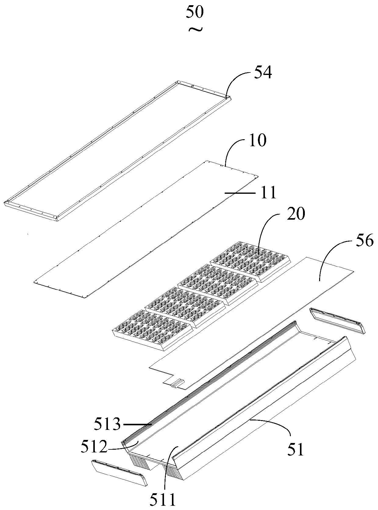
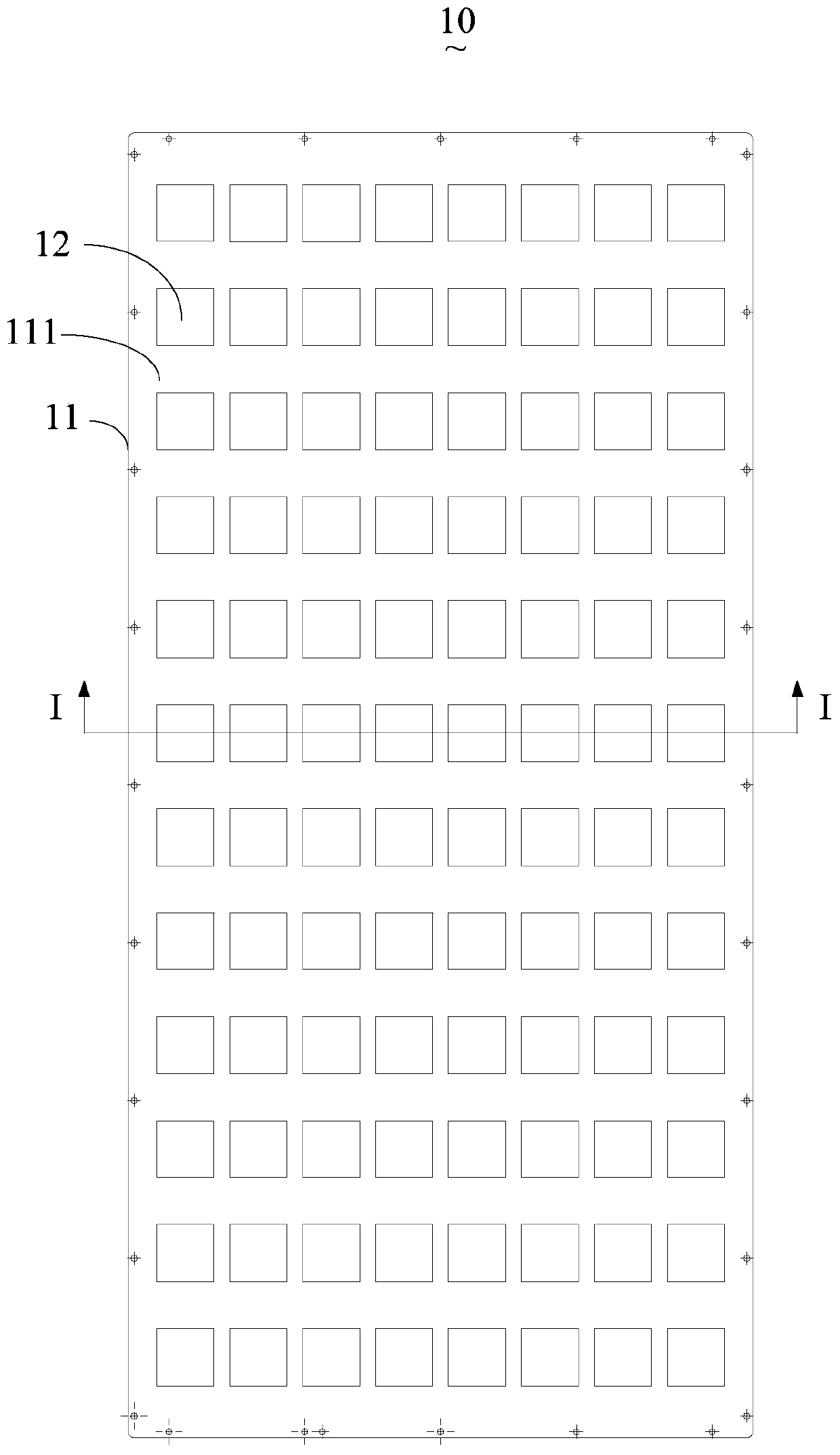
The application discloses an active antenna unit and an antenna unit for base stations. The active antenna unit for base stations includes a shell. The shell includes a bottom wall and side walls connected with the bottom wall to define a cavity with an opening at one end. Convex ribs are integrally formed on one side, away from the cavity, of the bottom wall. The bottom wall is provided with assembly holes. The depth of the assembly holes is greater than the thickness of the bottom wall, and the assembly holes extend into the convex ribs. The assembly holes of the application do not need to run through the bottom wall, so that the tightness of the shell is ensured, and signal leakage and interference in the shell are avoided.

Description

Technical field [0001] This application relates to the technical field of communication, and relates to an Active Antenna Unit (AAU) and an antenna unit used in a base station. Background technique [0002] With the rapid development of wireless communication technology, base station antennas are playing an increasingly important role in network coverage. The inventor of the present application has discovered through long-term research and development work that the existing active antenna unit includes a housing and a base station antenna, one end of the housing is provided with an opening, and the base station antenna is provided on the opening. The housing includes a bottom wall and a side wall connected to the bottom wall. The bottom wall is provided with a mounting hole. The depth of the mounting hole is greater than the thickness of the bottom wall. Therefore, the mounting hole punches through the bottom wall, causing signal leakage and interference in the housing. Summary ...

Claims


Application Information

Patent Timeline
Patent Type & Authority Applications(China)
IPC IPC(8): H01Q1/24H01Q1/42H01Q1/36H01Q1/02H01Q23/00
CPCH01Q1/246H01Q1/42H01Q1/36H01Q1/02H01Q23/00
Inventor 童恩东
Owner ANHUI TATFOOK TECH CO LTD
Why Eureka
Eureka Blog
Learn More