High tension switchgear capable of rapid connection
A high-voltage switchgear and quick-connect technology, which is applied to the parts of the connection device, the connection/disconnection of the connection device, and the connection, etc., can solve the problems affecting the normal use of the switchgear system and the long power outage time, so as to avoid long-term interruptions. The electrical and lap joint process is fast and the effect of improving the connection effect
- Summary
- Abstract
- Description
- Claims
- Application Information
AI Technical Summary
Problems solved by technology
Method used
Image
Examples
Embodiment 1
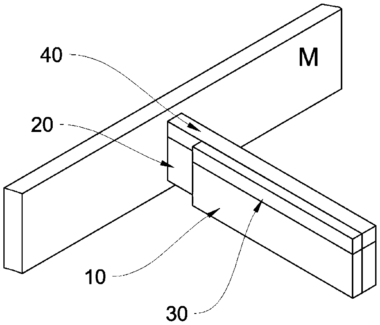
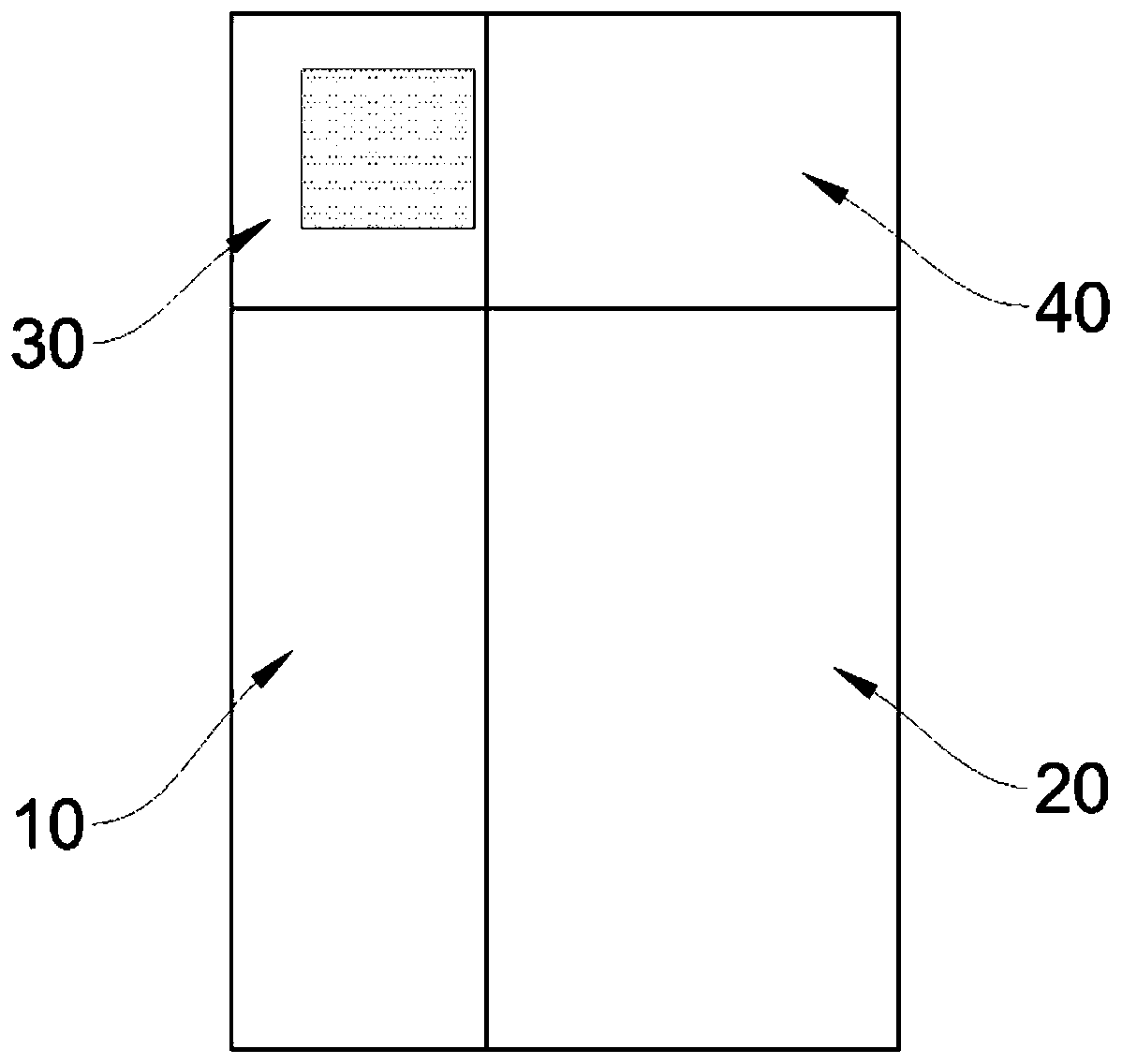
[0030] like Figure 1-Figure 2 As shown, a quick-connect high-voltage switchgear, the incoming copper bar 10 of the high-voltage switchgear and the busbar copper bar 20 are fixedly overlapped, and the busbar copper bar 20 is led out from the main busbar M and has a "T" shape structure , the upper side of the incoming line copper bar 10 is fixedly connected with an adsorption part 30, and the upper side of the corresponding busbar copper bar 20 is fixedly connected with an adsorption plate 40; the adsorption part 30 is an electromagnetic adsorption device with an electromagnet inside and is set There is a circuit channel for the power supply line to pass through; the adsorption surface of the adsorption part 30 and the adsorption plate 40 is parallel to the overlapping surface of the incoming copper bar 10 and the busbar copper bar 20 on the same plane.
[0031] The overall connection process of the high-voltage switchgear in this embodiment is as follows: move the high-voltage...
Embodiment 2
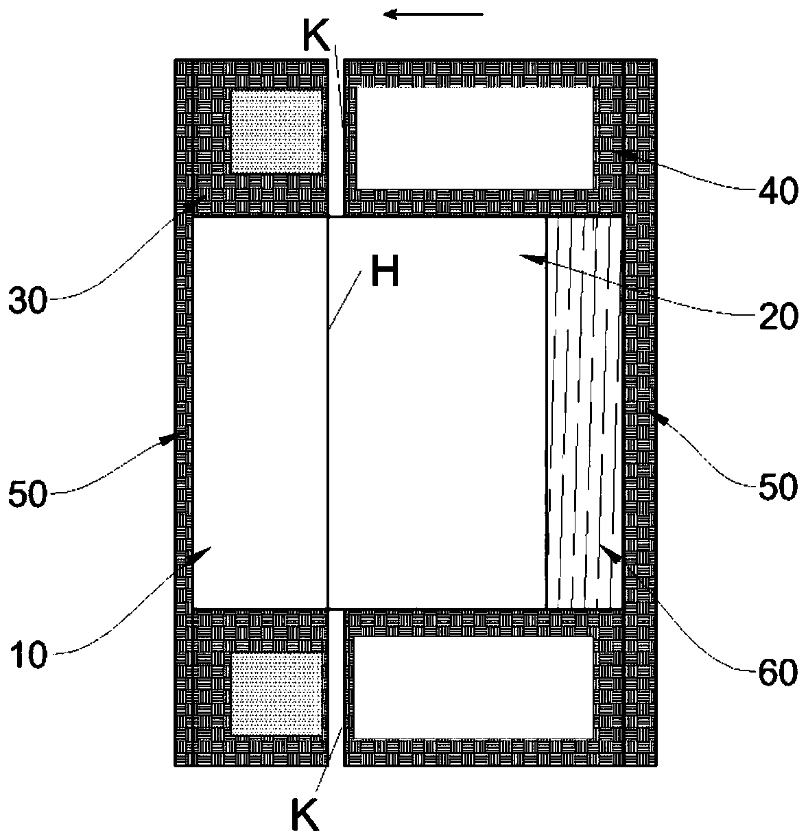
[0036] like image 3 As shown, this embodiment is optimized as follows on the basis of Embodiment 1: the adsorption part 30 and the adsorption plate 40 are respectively fixed on the upper and lower sides of the incoming copper bar 10 and the bus bar 20; The adsorption part 30 and the two adsorption plates 40 are respectively fixedly connected by the connecting bridge 50 located on the opposite surface of the overlapping surface H. Concave" shape. Further setting: the connecting bridge 50 of the two adsorption plates 40 is fixedly connected to the busbar copper bar 20 through the pressure spring 60, the two adsorption plates 40 are slidably arranged on both sides of the bus bar copper bar 20, and the adsorption surfaces K of the two adsorption plates 40 are located at The outer side of the overlapping surface H.
[0037] The connection process of the busbar copper bar 20 and the incoming line copper bar 10 in this embodiment is as follows: the electromagnetic adsorption devic...
Embodiment 3
[0041] Such as Figure 4 As shown, this embodiment is optimized as follows on the basis of Embodiment 2: the high-voltage switchgear also includes a signal activation device 70, and the signal activation device 70 includes a baffle vertically arranged outside the front end of the incoming copper bar 10 71 and block 72; the block 72 is an "L" shape with the same length of the two arms, and is hingedly arranged on the support plate 73 fixedly connected with the cabinet through a bending point; the baffle 71 follows the incoming line When the copper bar 10 moves or moves away from the end, it touches the inner surface of the stopper 72 to make it turn over. The support plate 73 is respectively provided with a pressure sensor 74 at the pressing part of the outer side of the stopper 72 after turning over.
[0042] Through the above-mentioned settings of this embodiment, the position of the incoming copper bar 10 is positioned and the electromagnetic adsorption device is turned on b...
PUM
 Abstract
Description
Claims
Application Information
 - R&D Engineer
- R&D Manager
- IP Professional
- Industry Leading Data Capabilities
- Powerful AI technology
- Patent DNA Extraction
Browse by: Latest US Patents, China's latest patents, Technical Efficacy Thesaurus, Application Domain, Technology Topic, Popular Technical Reports.
© 2024 PatSnap. All rights reserved.Legal|Privacy policy|Modern Slavery Act Transparency Statement|Sitemap|About US| Contact US: help@patsnap.com


