Device for installing insulating sheath on cable
A technology of cable insulation and insulating skin, which is used in insulation/armoured cable repair equipment, transportation and packaging, and transportation of filamentous materials, etc. It can solve problems such as cable discharge and leakage, and achieve safe transportation and construction. Effect
- Summary
- Abstract
- Description
- Claims
- Application Information
AI Technical Summary
Problems solved by technology
Method used
Image

Examples
Embodiment 1
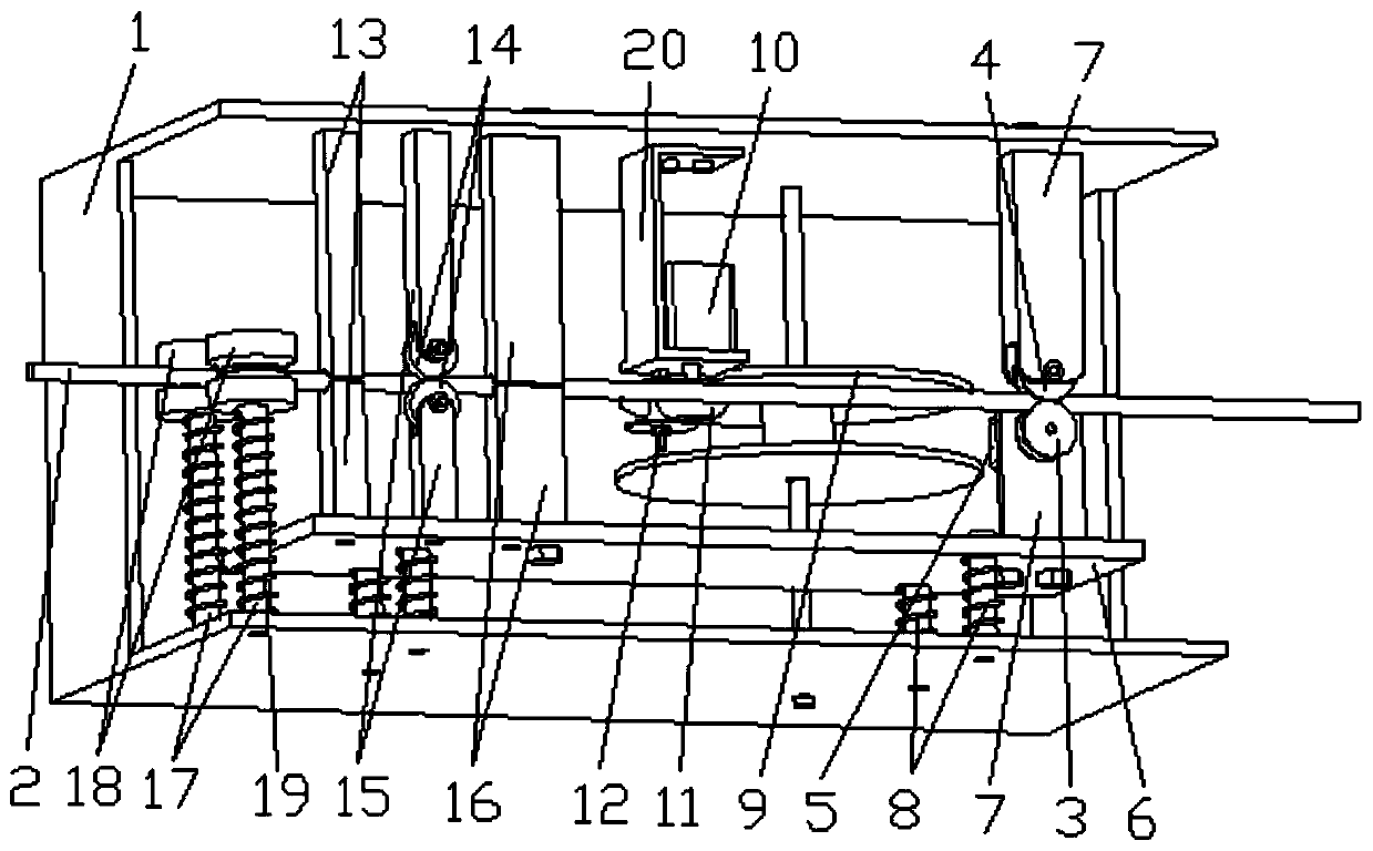
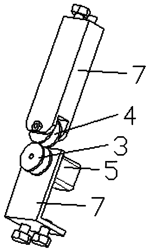
[0036]On the basis of the above-mentioned structure, in the present embodiment, the walking mechanism includes a walking driving wheel 3, a walking driven wheel 4 and a walking motor 5, and the walking driven wheel 4 is rotatably installed on the upper side of the cable 2 through the walking bracket 7, specifically The installation method is: the walking bracket 7 is fixed on the upper side of the box body 1 by bolts, and the upper side of the box body 1 and the walking bracket 7 are respectively provided with screw holes matched with the bolts; the lower end of the walking bracket 7 is provided with a U-shaped groove, The walking driven wheel 4 is installed in the above-mentioned U-shaped groove through the rotation of the rotating shaft. The two sides of the U-shaped groove are oppositely provided with through holes matched with the two ends of the above-mentioned rotating shaft. . The driving wheel 3 is rotatably installed on the lower side of the cable 2, and it can slide ...
Embodiment 2
[0038] On the basis of the embodiment, in this embodiment, a movable plate 6 is horizontally arranged in the box body 1, and the movable plate 6 is located below the cable 2, which can slide up and down and be positioned. Installed above the movable plate 6, the specific installation method is: the walking support 7 is vertically arranged in the casing 1, and its lower end is fixedly connected with the movable plate 6 by bolts, and the lower ends of the movable plate 6 and the walking support 7 are respectively provided with The screw hole that bolt cooperates; The upper end of walking support 7 is provided with U-shaped groove, and walking driving wheel 3 is rotatably installed in the above-mentioned U-shaped groove, and walking motor 5 is fixedly installed on the upper end of walking support 7 by bolt, and the walking motor 5 The casing and the walking support 7 are respectively provided with screw holes cooperating with the bolts; the driving end of the walking motor 5 is fi...
Embodiment 3
[0040] On the basis of Embodiment 2, in this embodiment, the lower side of the movable plate 6 is fixedly connected with the lower side of the box body 1 through a plurality of elastic parts 8 distributed at intervals, the structure is simple, and it is convenient to adjust the position of the movable plate 6, thereby Make the driving driving wheel 3 close to or away from the driven wheel 4, so as to fix or loosen the cable 2, the structure is simple, the operation is easy, and the time and effort are saved. Above-mentioned elastic member 8 comprises guide column and spring, and guide column is vertically fixed on the underside of casing 1, and its upper end passes movable plate 6 and extends to the top of movable plate 6, and movable plate 6 is provided with multiple and guiding The threaded hole is matched with the column; the upper end of the guide column is provided with thread, and the limit nut is threaded;
PUM
 Abstract
Description
Claims
Application Information
 - R&D
- Intellectual Property
- Life Sciences
- Materials
- Tech Scout
- Unparalleled Data Quality
- Higher Quality Content
- 60% Fewer Hallucinations
Browse by: Latest US Patents, China's latest patents, Technical Efficacy Thesaurus, Application Domain, Technology Topic, Popular Technical Reports.
© 2025 PatSnap. All rights reserved.Legal|Privacy policy|Modern Slavery Act Transparency Statement|Sitemap|About US| Contact US: help@patsnap.com