
Emergency self-propelled escape ladder structure

A self-propelled, emergency technology, applied in fire rescue, building rescue, life-saving equipment, etc., can solve problems such as injuries, ineffective use, and differences in falling speeds

Active Publication Date: 2021-06-08
汤博宇
View PDF0 Cites 0 Cited by
  • Summary
  • Abstract
  • Description
  • Claims
  • Application Information

AI Technical Summary

Problems solved by technology

In view of this, the general fire escape equipment must comply with the principle of no power available, so there are no power escape equipment such as escape slow down tubes (rescue bags) and slow down machines. The regulator is used to achieve the effect of emergency escape. Its principle is the same as that of the ancient pulley type ancient well. The pulley device is used and the centrifugal force brake is used to control the descending speed. The equipment cost is relatively low, but its operation is more complicated. When operating, personnel must hang and lower slowly outside the outer wall of a high-rise building. Personnel are directly exposed to extremely high environments, and they are prone to fear of heights and cannot perform operations. On the other hand, the operating procedures and formulas are too complicated, and it cannot be easily operated by non-trained personnel (such as firefighters), and the escape efficiency of its personnel is low (only one person can operate and use), so the use effect is not obvious
[0004] Based on the above, the structure of the rescue bag is the simplest in the escape equipment. It is tied in the high-strength cloth tube and installed at an appropriate position with a funnel-shaped ring belt with an elastic effect, and the ring belt has a slow-down effect, and personnel can quickly pass through the cloth Drill above the pipe and slide to the bottom of the pipe to escape. Although the escape efficiency is higher than that of the slow descending machine, it is often limited by the difference in the descending speed caused by the different body size and motor nerves of the escapers, which may cause the escapers to collide with each other. On the one hand, if the pipe installation position is too close to the wall, people may be injured by hitting the wall
For the escaping personnel with limited mobility, it is difficult to use the rescue bag to escape, so there are still disadvantages in the use of the rescue bag

Method used


Image

  • Emergency self-propelled escape ladder structure
  • Emergency self-propelled escape ladder structure
  • Emergency self-propelled escape ladder structure

Examples


Embodiment Construction

[0027] In order to achieve the above-mentioned purpose and effect, the technical means and the structure thereof adopted in the present invention are hereby illustrated in detail with respect to preferred embodiments of the present invention. Its structure and function are as follows, so as to fully understand.

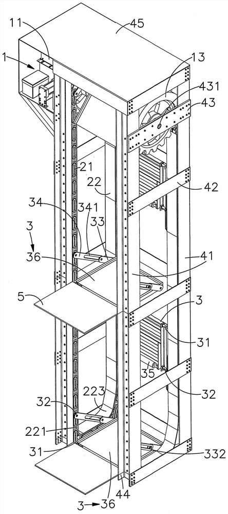
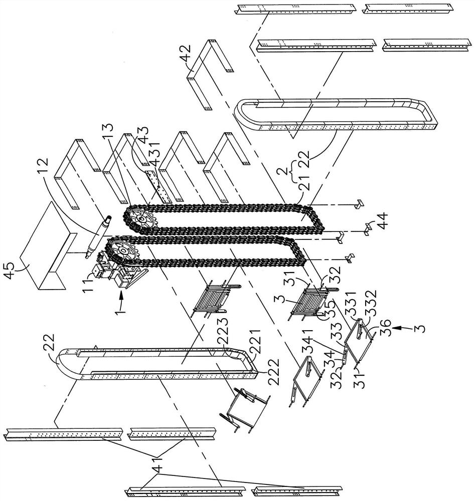
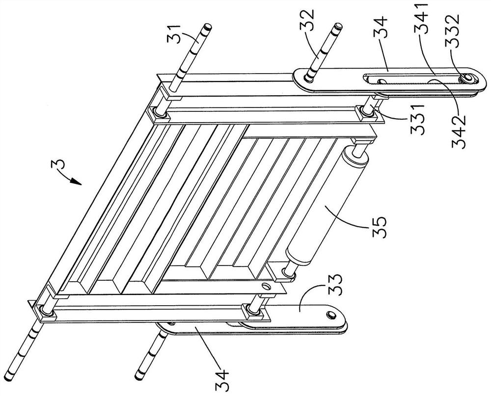
[0028] see Figure 1 to Figure 3 As shown, it is the three-dimensional appearance structure diagram, the three-dimensional exploded structure diagram and the detailed structure diagram of the bearing seat of the emergency self-propelled escape ladder of the present invention. It can be seen from these drawings that the main components of the present invention include the gravity deceleration device 1, The transmission unit 2 and the bearing seat 3 are summarized as follows:

[0029] The gravity reduction device 1 has a body 11 and a transmission shaft 12 extending therethrough, and the transmission shaft is inserted between a pair of gears 13 . The function of the gr...


PUM


Abstract

The present invention provides an emergency self -refuge ladder structure. It is a self -removed shelter ladder that runs through the high -rise building. It is connected to a transmission device with a one -gravity deceleration device.The pair of chain is equipped with a plural bearing seat. The plural carrier is used to accommodate the escape personnel, using the weight of the escape personnel to drive the chain and the bearer to move downward, and to slow down the device of the escape personnel through this gravity deceleration deviceThe decrease in the loading weight range is fixed and stable to achieve a stable and reliable escape equipment, which will be more able to ensure the purpose of safe escape from high floors and people who are inconvenient to safely escape.

Description

technical field [0001] The invention relates to an emergency self-propelled escape ladder structure, in particular to a self-propelled escape ladder erected inside or outside a tall building. Background technique [0002] Because the cities where human beings live are narrow and densely populated and the land prices are becoming more and more expensive, high-rise buildings are very common in urban floors. According to the current fire regulations, high-rise buildings must also have escape equipment for safety considerations as a benchmark! Every once in a while, there will always be building fire accidents where the building is not in a hurry to escape and cause heavy casualties. The main reason for the serious casualties is mostly insufficient escape measures; Insufficient escape measures are also to blame. For example, in the recent fire accident at the Carnival Building in Chiayi City, some victims died by jumping off the building in a hurry because they could not escape....

Claims


Application Information

Patent Timeline
Patent Type & Authority Patents(China)
IPC IPC(8): A62B1/02A62B5/00
CPCA62B1/02A62B5/00
Inventor 汤博宇
Owner 汤博宇
Learn More