
Road structure and construction method thereof

A technology of road structure and blind road, which is applied in the direction of roads, roads, road surfaces, etc., can solve the problems of occupying blind roads, insufficient publicity, and no great help for blind people walking on the road, so as to achieve the effect of convenient construction and processing

Inactive Publication Date: 2019-10-29
东莞市金建达建筑有限公司
View PDF9 Cites 5 Cited by
  • Summary
  • Abstract
  • Description
  • Claims
  • Application Information

AI Technical Summary

Problems solved by technology

[0004] The existing technical solutions in the above-mentioned have the following defects: in fact, due to reasons such as insufficient publicity among the common people, the large-scale construction of blind roads in domestic cities has not produced great help for the blind. And businessmen set up street stalls to occupy blind alleys; for blind people, if they can’t go from beginning to end on a blind alley, then this blind alley is useless, and the seemingly humanized blind alley on the sidewalk has become a “vase” to decorate the city , of no practical use

Method used


Image

  • Road structure and construction method thereof
  • Road structure and construction method thereof
  • Road structure and construction method thereof

Examples


Embodiment 1

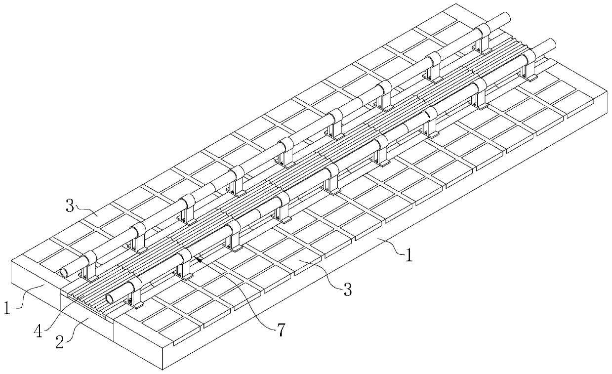
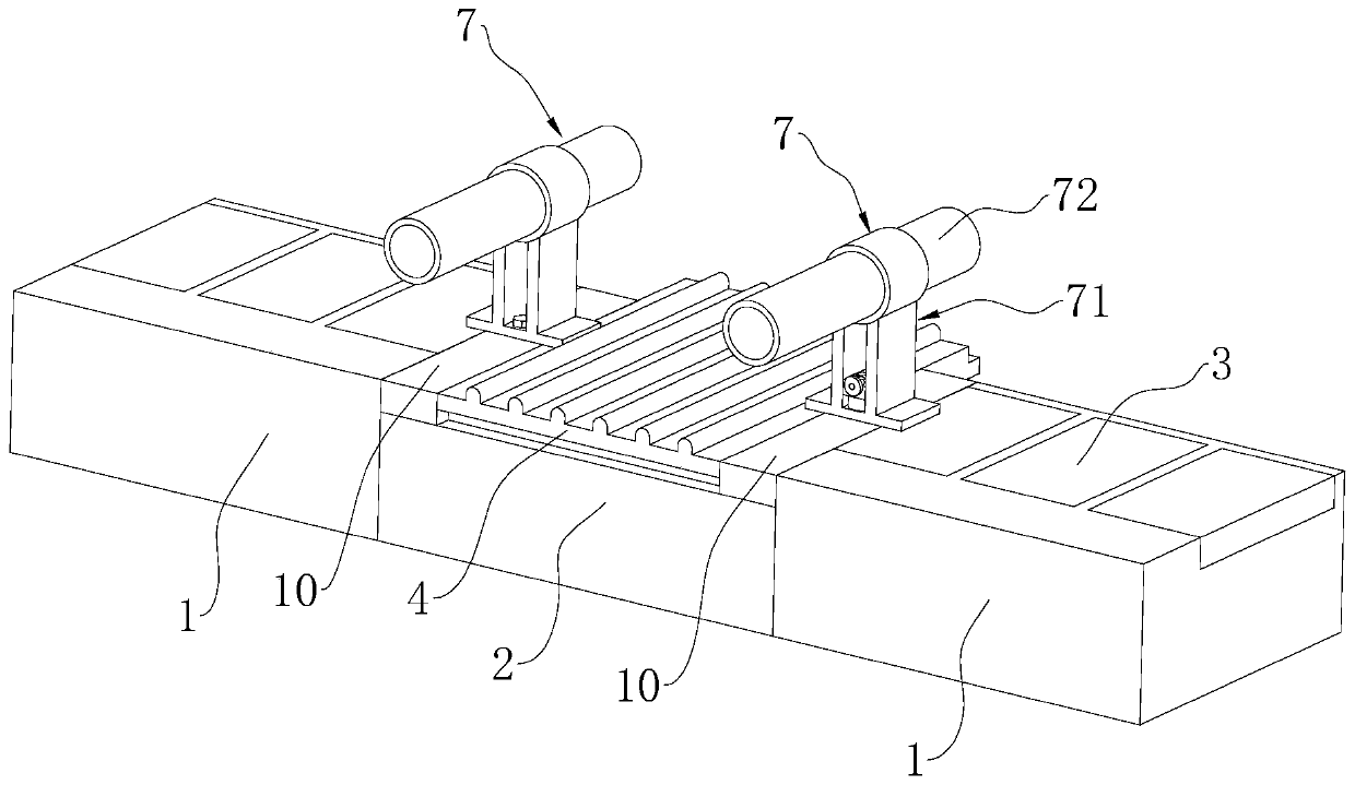
[0046] Embodiment 1: refer to figure 1 with 2 , is a road structure disclosed in the present invention, including a sidewalk 1 and a blind sidewalk 2, the blind sidewalk 2 is set in the middle of the sidewalk 1, and the sidewalk 1 and the blind sidewalk 2 are respectively laid with floor tiles 3 and blind sidewalks in sequence along their length directions Brick 4, floor tile 3 and blind walkway brick 4 are all solidified into one with sidewalk 1 and blind walkway 2 through cement slurry. refer to Figure 5 : wherein, one end of the tactile brick 4 along its length direction is fixed with a bump 5, and the other side is provided with a groove 6 for plugging of the bump 5, and the adjacent tactile brick 4 utilizes the plugging of the bump 5 and the groove 6 To connect together.

[0047] A concrete road 10 is respectively poured between the above-mentioned paving tiles 3 and the tactile paving bricks 4, the concrete paving 10 is arranged parallel to the blind walkway 2 and th...

Embodiment 2

[0052] Embodiment 2: a kind of construction method of road structure, with reference to figure 1 with 2 , including the following steps:

[0053] Step 1: Preliminary concrete laying is carried out on the road surface, and the sidewalk 1 and the blind sidewalk 2 are formed after the concrete is solidified;

[0054] Step 2: Fix the floor tiles 3 and the blind pavement bricks 4 on the sidewalk 1 and the blind walkway 2 respectively in order by using cement slurry;

[0055] Step 3, pouring a concrete road 10 between the floor tiles 3 and the tactile bricks 4, and during the pouring process, inserting the installation pipe 9 to the corresponding position;

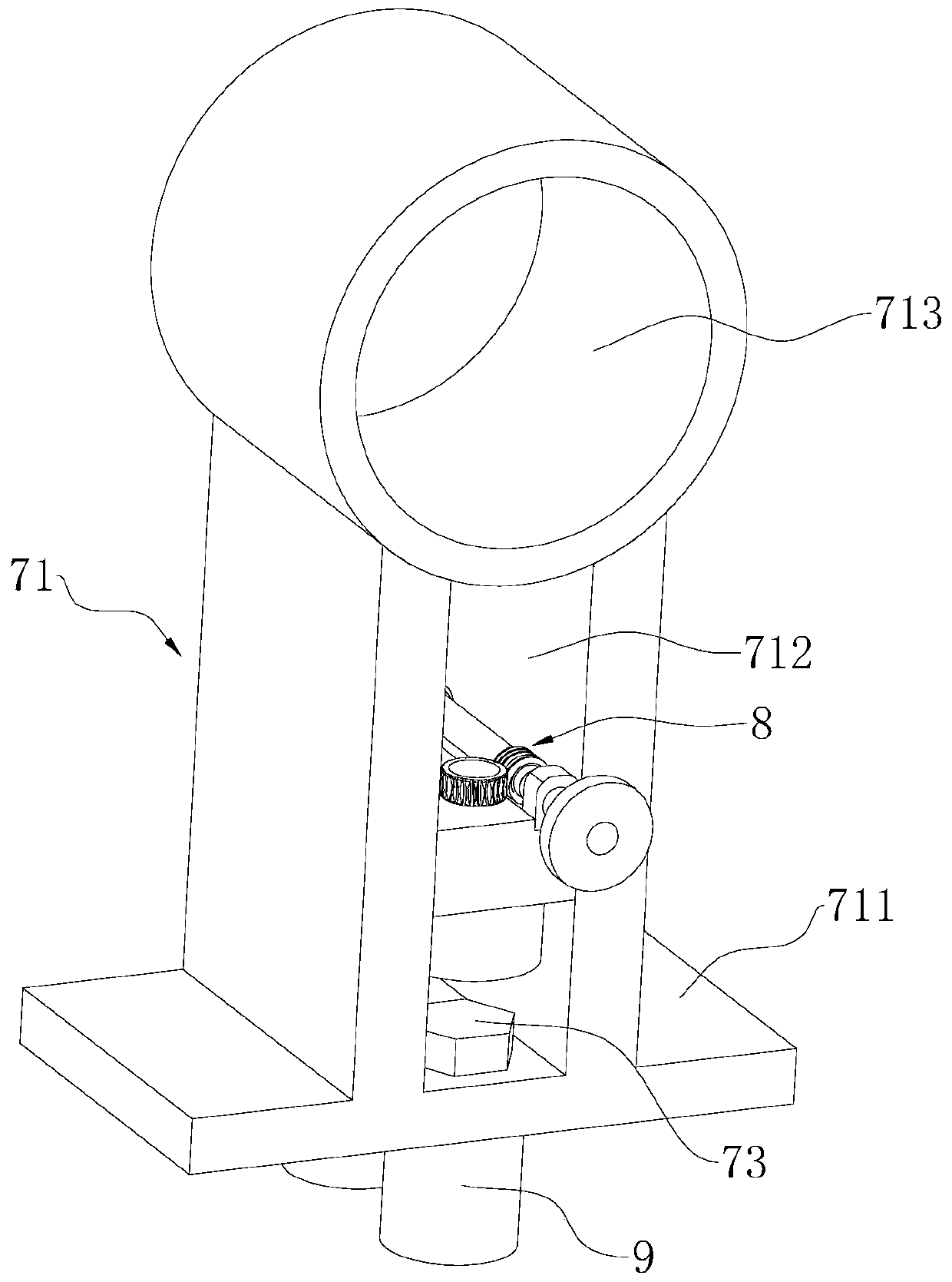
[0056] Step 4, after the floor tiles 3, the blind pavement bricks 4 and the concrete pavement 10 are fixed, the protective fence 7 that is welded together with the support frame 71 and the protective pipe 72 is set at the starting position of the blind walkway 2, and the support frame 71 and the The installation pipe 9 positi...


PUM


Abstract

The invention relates to a road structure and a construction method thereof. The road structure comprises a sidewalk and a blind lane arranged in the middle of the sidewalk; floor tiles are laid on the sidewalk; blind bricks are laid on the blind lane; protective fences are correspondingly arranged on the two sides of the width direction of the blind lane; the protective fences comprise a plurality of supporting frames and protective pipes, wherein the supporting frames are mounted on the ground, and the protective pipes are inserted in the supporting frames; concrete lanes are arranged between the floor tiles and the blind bricks; a plurality of mounting pipes are fixed in the concrete lanes; the interiors of the mounting pipes are hollow and provided with internal threads; and supportingframes are arranged above the mounting pipes, and fastening bolts matched with the threads of the mounting pipes are arranged on the supporting frames in a penetrating manner. The road structure hasthe effects that the occupation of outside sundries to the blind lane is reduced, and the running safeties of blind people are guaranteed.

Description

technical field [0001] The invention relates to the technical field of blind roads, in particular to a road structure and a construction method thereof. Background technique [0002] At present, blind roads are road facilities specially designed to help blind people walk. Blind roads are generally paved with two types of bricks, one is strip-shaped guiding bricks, which guide blind people to move forward with confidence, which is called walking blind road; To remind the blind. . [0003] The existing Chinese patent with the publication number CN109610267A discloses a blind sidewalk guided by a magnet, which includes a road body formed by laying several paving bricks. The road body includes a connected straight road and a turning road. The first road and the second road located on both sides of the first road, a number of straight magnets are arranged in the second road, the straight magnets are arranged along the edge of the first road, and the magnetic pole direction of ...

Claims


Application Information

Patent Timeline
Patent Type & Authority Applications(China)
IPC IPC(8): E01C5/00E01C15/00E04H17/14
CPCE01C5/00E01C15/00E04H17/14
Inventor 郑焕杰
Owner 东莞市金建达建筑有限公司
Learn More