
Load box integrating test force application and engineering pile reinforcement

A technology of load boxes and engineering piles, which is applied in foundation structure engineering, foundation structure testing, construction, etc., can solve problems such as engineering pile breakage, unquantifiable acceptance, disconnection, etc., to ensure filling rate, ensure compactness, and improve The effect on success rate

Pending Publication Date: 2019-10-29
NANCHANG YONGQI TECH DEV +1
View PDF0 Cites 3 Cited by
  • Summary
  • Abstract
  • Description
  • Claims
  • Application Information

AI Technical Summary

Problems solved by technology

The problems existing in the work of this type of load box are: 1. After the self-balancing static load test of the foundation pile, the liquid between the cylinder and the piston of the load box is filled with never solidified liquid, which causes the pile to squeeze under the vertical compression state of the project. 2. As a part of the engineering pile, the steel cage connected with the load box is disconnected, and the force transmission of the pile is carried out through the load box. However, the current load box cylinder and the piston are pulled out in the vertical direction Therefore, the load box lacks the anti-pull function; 3. The reinforcement cages at the upper and lower ends of the load box are disconnected, which seriously affects the effective downward transmission of the upper load box; 4. After the load box is applied, it must be Caused the fracture of the engineering pile where the force was applied, and the reinforcement through the lower displacement pipe infusion grouting could not be quantitatively accepted

Method used


Image

  • Load box integrating test force application and engineering pile reinforcement
  • Load box integrating test force application and engineering pile reinforcement
  • Load box integrating test force application and engineering pile reinforcement

Examples


Embodiment Construction

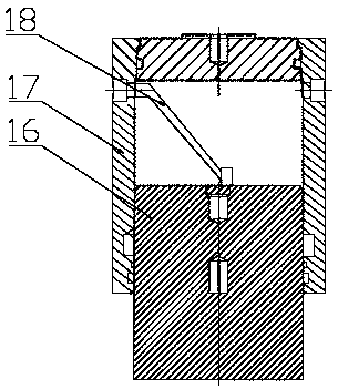
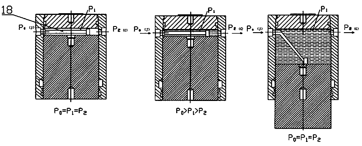
[0031] Attached below Figure 1-8 The present invention is further described:

[0032] An integrated load box integrating test force and engineering pile reinforcement, including a load box device and a detection device;

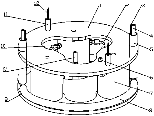
[0033] Such as figure 1 , 6 As shown, the load box device includes: upper base 1, hydraulic pipe 2, lower displacement wire 3, outer grouting pipe 4, outer grouting pipe sheath 5, hydraulic pipe 6, hydraulic pipe 6', jack 7, U-shaped bottom Pipe 8, lower base 9, hydraulic pipe and cylinder connecting piece 10, upper displacement wire sheath 11, upper displacement wire 12, joint 13, lower displacement wire fixing ring 14, joint base 15.

[0034] Such as figure 2 As shown, the upper base 1 is arranged opposite to the lower base 9, and can move up and down under the action of the jack 7; the upper base 1 is provided with a through hole for the upper displacement wire sheath 11 and the outer grouting pipe sheath 5 to pass through , the upper displacement w...


PUM


Abstract

The invention relates to a novel self-balancing load box, in particular to an integrated load box which provides load application force during static load test pile detection and reinforces an engineering pile after a detection test is finished, and belongs to the field of civil engineering. A load box integrating test force application and engineering pile reinforcement comprises a connecting base, hydraulic pipes and a jack structure, wherein a connecting plate comprises an upper base and a lower base which are oppositely arranged; the jack structure is arranged between the upper base and the lower base to move; there are a plurality of hydraulic pipes, and one hydraulic pipe communicates with an liquid inlet and an liquid inlet device to form a loading liquid path passage, another hydraulic pipe communicates with an liquid outlet and an slurry inlet device to form a grouting liquid path passage, and other hydraulic pipes communicates with the liquid inlets and liquid outlets adjacent the jack structure. The invention has the following advantages: firstly, the effectiveness of grouting in a cylinder is improved; secondly, the compactness of the grouting in the cylinder can be ensured; thirdly, the filling rate of the grouting in the displacement clearance of the upper and lower section piles are ensured; fourthly, the pile body strength of the pile foundation is improved, andthe foundation pile reinforcing effect is achieved; and finally, the vertical bearing capacity of the foundation pile can be continuously transmitted.

Description

technical field [0001] The invention relates to a novel self-balancing load box, in particular to an integrated load box that provides load application during static load test pile detection and reinforces engineering piles after the detection test, and belongs to the field of civil engineering. Background technique [0002] When the current self-balancing load box works, the load box is buried at the bottom of the cast-in-situ pile or at the calculated pile body position, and a displacement tube (rod) and a hydraulic tube are connected to the ground, and the displacement rod is connected to the sensor of the ground measurement system. The hydraulic pipe is connected to the loading oil pump. During the test, the loading oil pump exerts pressure on the inner cavity of the load box through the hydraulic pipe, and the top and bottom of the box are pushed apart to generate upward and downward thrusts, thereby mobilizing the side resistance and end resistance of the soil around t...

Claims


Application Information

Patent Timeline
IPC IPC(8): E02D33/00E02D15/04
CPCE02D15/04E02D33/00E02D2250/003
Inventor 钱勇钱崑刘凯李丹易春昌
Owner NANCHANG YONGQI TECH DEV
Learn More