Equipment for drying materials by using air energy

An air energy and material technology, applied in drying, drying machine, drying solid materials and other directions, can solve the problems of cumbersome steps and low drying efficiency, and achieve high drying efficiency, increase heating area, and convenient use and operation. Effect

Active Publication Date: 2019-10-29
ANHUI OURUIDA ELECTRICAL APPLIANCE TECH
View PDF1 Cites 2 Cited by
  • Summary
  • Abstract
  • Description
  • Claims
  • Application Information

AI Technical Summary

Problems solved by technology

[0005] The purpose of the present invention is to provide a device that utilizes air energy to dry materials, so as to...

Method used


Image

  • Equipment for drying materials by using air energy
  • Equipment for drying materials by using air energy
  • Equipment for drying materials by using air energy

Examples


Embodiment Construction

[0026] It should be understood that the specific embodiments described here are only used to explain the present invention, not to limit the present invention.

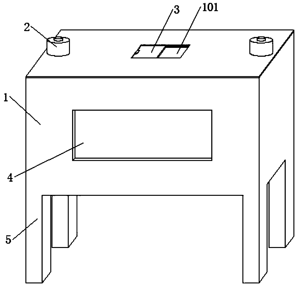
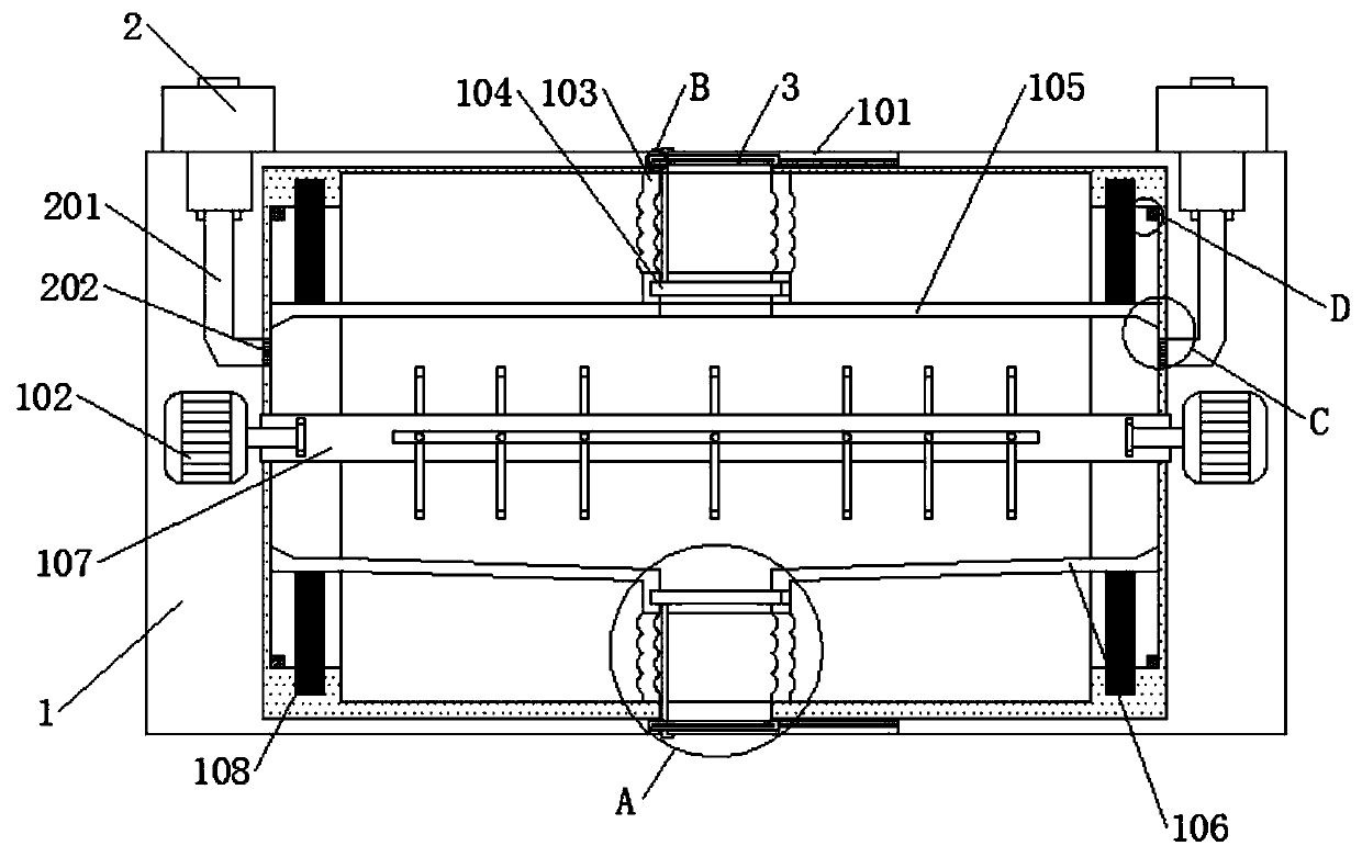
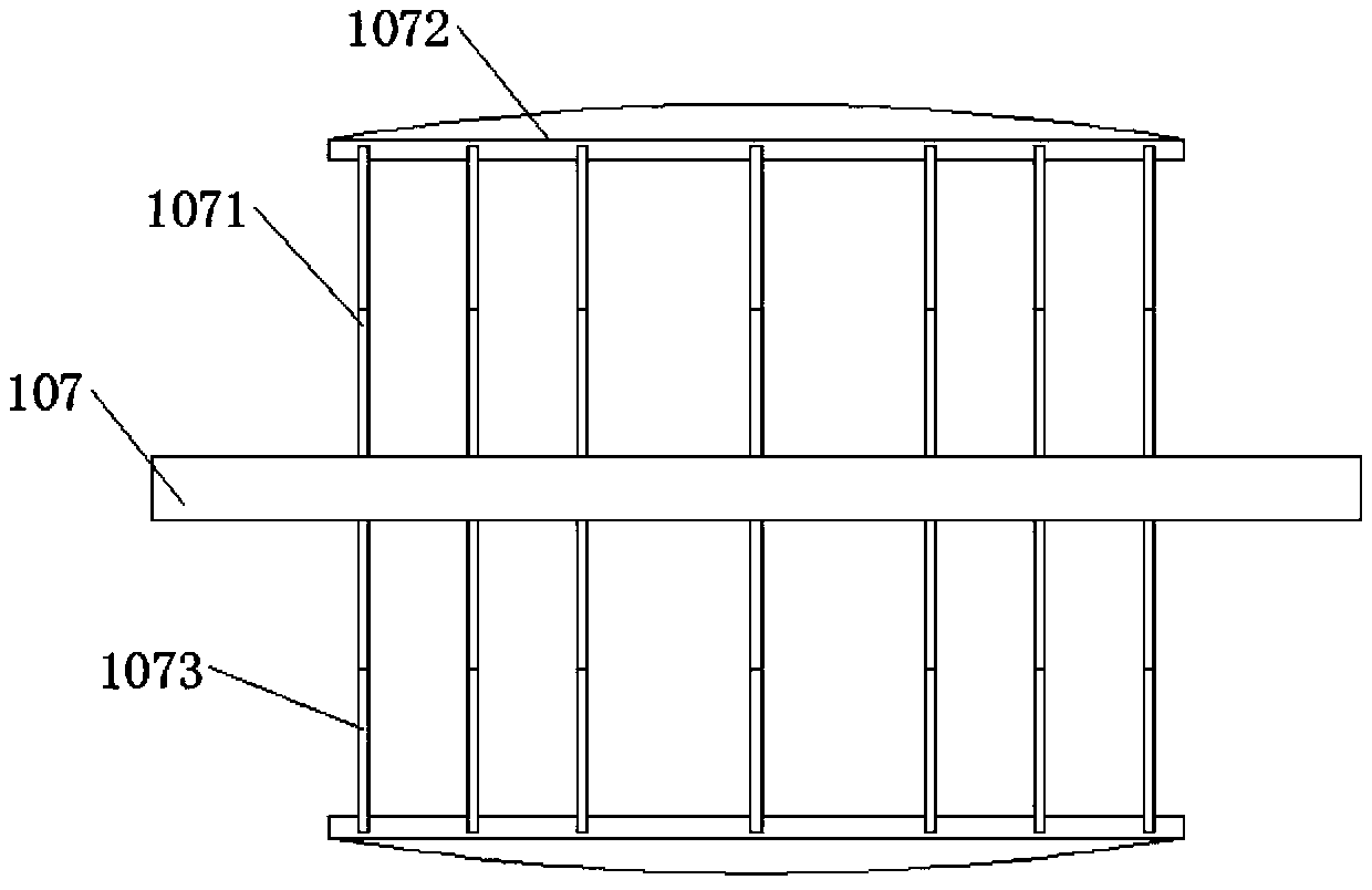
[0027] See attached figure 1 to attach Figure 7 , a device that uses air energy to dry materials, including: a casing 1, a chute 101, a low-speed motor 102, a hose 103, an inner door 104, a co-moving rope 1041, a top plate 105, a bottom inclined plate 106, and a rotating column 107, support rod 1071, arc plate 1072, arc rod 1073, spring column 108, sponge block 109, insulation layer 1010, heat pump dryer 2, air duct 201, filter screen 202, transmission door body 3, sliding plate 301, observation The window 4 and the bottom column 5 are embedded with a heat pump dryer 2 on the left and right sides of the top of the shell 1, and the bottom of the heat pump dryer 2 is fixedly connected with an air guide tube 201, and the bottom end of the inner wall of the air guide tube 201 is embedded with a filter screen 202, An ob...


PUM


Abstract

The invention provides equipment for drying materials by using air energy. The equipment comprises a housing, heat pump drying machines, a driving door body and sill pillars, wherein the heat pump drying machines are respectively embedded into the left and right sides of the top end of the housing, air guide pipes are fixedly connected to the bottom ends of the heat pump drying machines, filter screens are embedded into the bottom ends of the inner walls of the air guide pipes, an observation window is embedded into the middle of the front end of the housing, the sill pillars are integrally arranged on four corners of the bottom end of the housing, chutes are respectively embedded into the middle of the upper and lower ends of the housing, the driving door body is movably connected to themiddle of the chutes, sliding plates are respectively arranged in the middle of the front and back ends of the driving door body, a comoving rope is fixedly connected to the middle of the left end ofthe inner side of the driving door body, low-speed motors are respectively embedded into the middle of the left and right sides of the inner wall of the housing, rotating posts are fixedly connected to the low-speed motors respectively, and arc plates are fixedly connected to the front and back ends of the outer walls of the rotating posts respectively by virtue of support rods. The whole device has the advantages of structural stability, simple material drying step, convenience in use and operation, good drying effect, energy conservation and environmental friendliness.

Description

technical field [0001] The invention belongs to the technical field of energy-saving drying equipment for materials, and in particular relates to equipment for drying materials by using air energy. Background technique [0002] With the advancement of science and technology and the development of society, material drying equipment is used more and more widely. Drying equipment using air energy has a good prospect. Heat pumps are a type of air energy. Heat pumps are essentially a kind of heat The lifting device and the high temperature heat pump drying unit use the reverse Carnot principle to absorb heat from the surrounding environment and transfer it to the heated object (object with higher temperature). Carnot cycle works, the only difference is the operating temperature range is not the same. [0003] Existing equipment that uses air energy to dry materials usually sets up a special room, and then puts the materials on the racks in a flat manner, and then performs the dr...

Claims


Application Information

Patent Timeline
IPC IPC(8): F26B11/16F26B21/00F26B25/04F26B25/10F26B25/12
CPCF26B11/16F26B21/002F26B25/04F26B25/10F26B25/12
Inventor 马学天
Owner ANHUI OURUIDA ELECTRICAL APPLIANCE TECH
Why Eureka
Try Eureka