
Wafer package map error correction system solution

An error correction system and wafer packaging technology, which is applied in the manufacture of electrical components, circuits, semiconductors/solid-state devices, etc., can solve problems such as chip testing failures, and achieve the effect of preventing wafer packaging failures

Active Publication Date: 2021-06-25
PAYTON TECHNOLOGY (SHENZHEN) CO LTD
View PDF5 Cites 0 Cited by
  • Summary
  • Abstract
  • Description
  • Claims
  • Application Information

AI Technical Summary

Problems solved by technology

[0006] The solution of the wafer packaging map error correction system of the present invention is aimed at the chip packaging placement station. When the chip is captured, the bad product caused by the pairing of the actual wafer and the map is produced as a good product, resulting in a defective rate of chip testing. problem, the following solutions are proposed:

Method used


Image

  • Wafer package map error correction system solution
  • Wafer package map error correction system solution
  • Wafer package map error correction system solution

Examples


Embodiment Construction

[0021] Wafer packaging map error correction system solution, aiming at the placement station of chip packaging, when the chip is captured, the bad products caused by the pairing of the actual wafer and the map are regarded as good products, which leads to the problem of chip test defect rate. The solution is as follows:

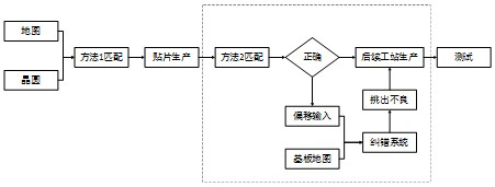
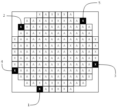
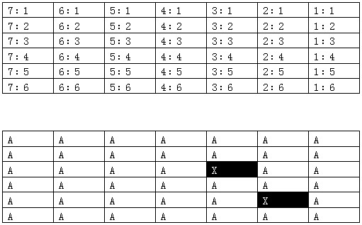
[0022] like figure 1 As shown, the map and the wafer are matched in method 1, and then enter the SMT production. At this time, the substrate map is added to the equipment machine, and the coordinates of each product on the substrate corresponding to the wafer map are recorded. At the same time, after the SMT production, enter the method 2 matching. If the matching is passed through method 2, the map and the wafer are matched correctly, and then enter the subsequent station for production, and then test; if the matching is not passed through method 2, the offset input is performed on the wafer map, and then enters the error correction system with the substrat...


PUM


Abstract

The invention discloses a solution to a wafer packaging map error correction system. A substrate map is added to the SMT station equipment, and the coordinates of each product on the substrate corresponding to the wafer map are recorded; when it is found that the map is incorrectly matched, bad chips are mixed in. At the same time, you only need to input the offset information + substrate map into the error correction system. Through the calculation of the error correction system, it can automatically display which products on the substrate are defective, and then according to the system prompt information, the defective products will be deducted to avoid further damage to the products. Loss.

Description

technical field [0001] The invention relates to a solution to an error correction system for a wafer package map. Background technique [0002] In the diebonding station of chip packaging, when picking up the chip, the placement machine will pick up the wafer according to the map (wafermapping) tested before the wafer leaves the factory. It is guaranteed that only good products will be taken, and bad products will not be picked up. , which requires the machine to match the actual wafer with the map before picking up the crystal. If the two match incorrectly, it will cause bad products to be produced as good ones, and subsequent tests will be defective. [0003] With the development of multi-layer chip stacking technology, more and more chips are stacked together. Multi-layer chip packaging requires multiple placements, and each placement requires matching of wafers and maps. , and as long as one of the matching errors cannot be found in time, the loss will be huge. For exam...

Claims


Application Information

Patent Timeline
Patent Type & Authority Patents(China)
IPC IPC(8): H01L21/67H01L21/68H01L21/56
CPCH01L21/561H01L21/67259H01L21/68
Inventor 刘传喜陈小钢
Owner PAYTON TECHNOLOGY (SHENZHEN) CO LTD
Learn More