Camera monitoring system and method of calibrating a camera monitoring system for monitoring a patient in a bore based medical system

A monitoring system and camera technology, which is used in radiological diagnostic instruments, medical equipment, stereo systems, etc., can solve problems such as difficulty in obtaining accurate patient monitoring.

Pending Publication Date: 2019-10-29
VISION RT LTD
View PDF7 Cites 0 Cited by
  • Summary
  • Abstract
  • Description
  • Claims
  • Application Information

AI Technical Summary

Problems solved by technology

[0009] Thus, with existing solutions, it is difficult to obtain accurate monitoring of the patient while the patient is inside the bore

Method used


Image

  • Camera monitoring system and method of calibrating a camera monitoring system for monitoring a patient in a bore based medical system
  • Camera monitoring system and method of calibrating a camera monitoring system for monitoring a patient in a bore based medical system
  • Camera monitoring system and method of calibrating a camera monitoring system for monitoring a patient in a bore based medical system

Examples


Embodiment 1

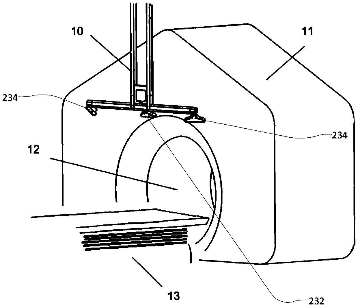
[0166] Embodiment 1: A method of calibrating a patient monitoring system for monitoring the positioning of a patient at first and second locations spaced apart by a fixed distance, the method comprising:

[0167] providing a monitoring system operable to obtain images of the patient proximate to the first and second locations;

[0168] providing a calibration object having a first set of calibration marks and a second set of calibration marks, the first set of calibration marks being offset from the second set of calibration marks by a distance corresponding to the distance between the first and second positions;

[0169] positioning the calibration object such that a first set of calibration marks is located adjacent a first location and a second set of calibration marks is located adjacent a second location;

[0170] obtaining images of the first and second sets of calibration marks using the monitoring system; and

[0171] The monitoring system is calibrated based on the a...

Embodiment 2

[0172] Embodiment 2: The method of Embodiment 1, wherein the monitoring system comprises a plurality of 3D cameras, wherein at least one 3D camera is configured to capture images of objects near the first location and at least one 3D camera is configured to capture images of objects near the second location Image.

Embodiment 3

[0173] Embodiment 3: The method according to embodiment 2, wherein the 3D camera comprises a 3D camera selected from the group consisting of: a stereo camera; a 3D time-of-flight camera and a 3D camera utilizing structured light to project onto the surface of the monitored object.


PUM


Abstract

The invention provides a camera monitoring system and a method of calibrating a camera monitoring system for monitoring a patient in a bore based medical system. There is provided a 3D camera which comprises a first and a second image sensor mounted on a circuit board, wherein the first and second image sensors are mounted on opposing surfaces of the circuit board. The circuit board is contained within a housing which also contains a first and a second mirror positioned within the housing so that the first image sensor is presented with a first view of an object to be imaged via the first mirror and second image sensor is presented with a second view of an object to be imaged via the second mirror. The camera further comprises a projector operable to project light onto an object surface tobe imaged by the first and second image sensors.

Description

technical field [0001] The present invention relates to 3D camera systems. More specifically, the present invention relates to a 3D camera system for monitoring the positioning and movement of a patient during scanning and / or treatment. The invention is particularly suitable for use with radiotherapy equipment and computed tomography (CT) scanners and the like, where patient movement or the detection of eg irregular breathing is important for successful treatment. Furthermore, the present invention relates to a method of calibrating a patient monitoring system consisting of the 3D camera system disclosed herein. The method is suitable for calibrating patient monitoring systems that monitor the patient's position with a very high accuracy, such as is required for patient monitoring systems for monitoring the patient's position and position during radiotherapy. Background technique [0002] Imaging techniques in the field of medical applications such as MR and CT imaging are...

Claims


Application Information

Patent Timeline
IPC IPC(8): H04N13/275H04N13/246G16H40/40
CPCH04N13/275H04N13/246G16H40/40A61N5/1049A61N2005/1059H04N13/239H04N13/25H04N13/254A61B2090/3618H04N13/236A61B5/1128A61B6/527A61N5/1075G06T7/0014G06T2200/04
Inventor G·M·黑尔
Owner VISION RT LTD
Why Eureka
Try Eureka