Indoor dust suppression device for construction site

A construction site and dust reduction device technology, applied in the direction of using liquid separation agent, suction nozzle, and dispersed particle separation, etc., can solve the problems of dust treatment that cannot be grounded, and achieve the effects of improving dust reduction efficiency, expanding the area, and reducing friction

Pending Publication Date: 2019-11-01
中建河图建设有限公司
View PDF1 Cites 0 Cited by
  • Summary
  • Abstract
  • Description
  • Claims
  • Application Information

AI Technical Summary

Problems solved by technology

In the above-mentioned patent, the process of spraying water is used to remove dust on the construction site, but only spraying water can only reduce the dust in the air, and cannot treat the dust on the ground

Method used


Image

  • Indoor dust suppression device for construction site
  • Indoor dust suppression device for construction site
  • Indoor dust suppression device for construction site

Examples


Embodiment 1

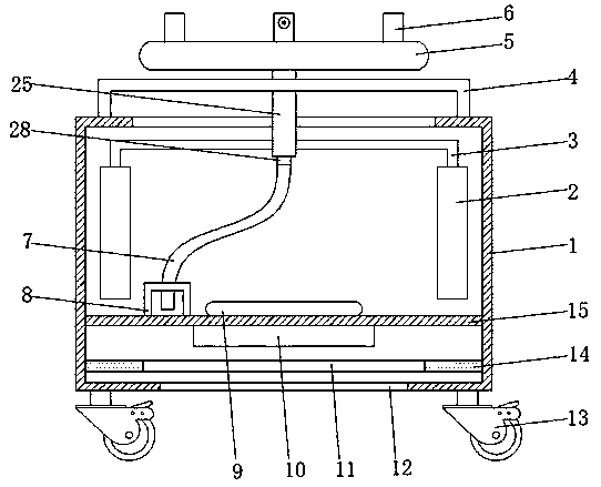
[0029] refer to Figure 1-6 , an indoor dust suppression device for a construction site, comprising a casing 1, the bottom end between the inner walls on both sides of the casing 1 is fixedly connected with a partition 15 by bolts, and the partition 15 separates the casing 1 into water storage at the top of the partition 15 chamber and the dust suction chamber at the bottom of the partition 15, the bottom of the partition 15 is fixedly connected with a negative pressure fan 10 by bolts, and the shell 1 is fixedly connected with a frame 14 by bolts between the inner walls of both sides of the dust suction chamber, and the frame 14 It is located below the negative pressure fan 10, and the middle part of the frame 14 is provided with an opening. The frame 14 is fixedly connected with an isolation pad 11 by bolts at the opening. The material of the isolation pad 11 is a porous material. There is a dust suction port 12 at the bottom, so the negative pressure can be generated by the...

Embodiment 2

[0036] refer to Figure 7 , an indoor dust suppression device for a construction site. Compared with Embodiment 1, in this embodiment, in order to make the replacement and cleaning of the isolation pad 11 more convenient, the frame 14 includes a first frame 1401 and a second frame 1402, the first frame 141 and the second frame 1402. The hinges 26 are fixedly connected by bolts between the second frames 142, and the four corners of the top of the second frame 142 are fixedly connected with fixing piles 27 by bolts, and the four corners of the spacer 11 are all provided with fixing holes, and the fixing piles 27 is adapted to the fixing hole, so the spacer 11 can be easily removed by separating the first frame 141 and the second frame 142 after use, thereby bringing convenience to the replacement and cleaning of the spacer 11.

[0037] When in use: first inject clear water into the water storage chamber, then take out the frame 14 and separate the first frame 141 and the second ...


PUM


Abstract

The invention belongs to the technical field of building equipment and particularly relates to an indoor dust suppression device for a construction site. In view of the problem that the existing devices are not comprehensive enough during indoor dust suppression, a scheme as follows is proposed at present: the indoor dust suppression device comprises a shell, wherein a partition plate is fixedly connected to a bottom end, between internal walls of two sides, of the shell, the shell is divided into a water storage chamber located at the top end of the partition plate and a dust suction chamberlocated at the bottom end of the partition plate by the partition plate, the bottom end of the partition plate is fixedly connected with a negative-pressure blower, a framework is fixedly connected tothe shell between internal walls of two sides of the dust suction chamber and is located below the negative-pressure blower, and an opening is formed in the middle part of the framework. According tothe indoor dust suppression device for the construction site, through arranging the negative-pressure blower and an isolating pad, negative pressure can be generated through the negative-pressure blower, so that dust on the ground can be sucked into the dust suction chamber from a dust suction port; and meanwhile, the isolating pad is required to be bedewed with water before using the device, sothat the dust will be blocked by the isolating pad when the dust enters the dust suction chamber, and an operating state of the negative-pressure blower cannot be affected by the dust.

Description

technical field [0001] The invention relates to the technical field of construction equipment, in particular to an indoor dust suppression device for a construction site. Background technique [0002] A large amount of dust is often generated during construction on a construction site. Outdoor dust is more difficult to deal with due to the influence of external airflow, but indoor dust can be treated with some equipment to reduce dust, so as to prevent indoor personnel from inhaling a large amount of dust. . [0003] After searching, the Chinese patent application number is 201611176865.9, which discloses a dust removal equipment for construction sites, which includes a hollow box with openings at both ends. A water pump and a booster device are installed at one opening of the box. One end of the water pump passes through the The pipeline is connected with the external water source pipeline, the other end of the water pump is connected with one end of the supercharging devi...

Claims


Application Information

Patent Timeline
Patent Type & Authority Applications(China)
IPC IPC(8): B01D47/08A47L9/02
CPCA47L9/02B01D47/08
Inventor 王凡钱光华林少龙徐盖陈子杰陈登意张敏
Owner 中建河图建设有限公司
Why Eureka
Try Eureka