
A helical gear plastic part demoulding device and method with ejector assisting cavity rotation

The technology of demolding device and helical gear is applied in the field of demoulding device for helical gear plastic parts, which can solve the problems of bearing selection, troublesome installation and disassembly, complicated mold structure, etc., and achieves the effect of compact structure, improved molding efficiency and perfect function.

Active Publication Date: 2021-03-19
CHANGZHOU INST OF TECH
View PDF8 Cites 0 Cited by
  • Summary
  • Abstract
  • Description
  • Claims
  • Application Information

AI Technical Summary

Problems solved by technology

The thrust bearing assists the helical gear plastic part or the cavity rotation of the formed helical tooth shape to realize the demoulding of the helical gear plastic part after molding, which can reduce the friction and wear of the molded parts and improve the effectiveness of the helical gear plastic part from the mold. However, the mold structure is complex, and the selection, installation, and disassembly of bearings are troublesome. At the same time, the characteristics of the lubricating oil in the bearing and the requirements of the operating environment (temperature) need to be considered. Molding quality of gear plastic parts

Method used


Image

  • A helical gear plastic part demoulding device and method with ejector assisting cavity rotation
  • A helical gear plastic part demoulding device and method with ejector assisting cavity rotation
  • A helical gear plastic part demoulding device and method with ejector assisting cavity rotation

Examples


Embodiment Construction

[0031] The present invention will be described in further detail below in conjunction with the accompanying drawings.

[0032] This embodiment is used for injection molding mould, and mold is installed on the horizontal injection machine.

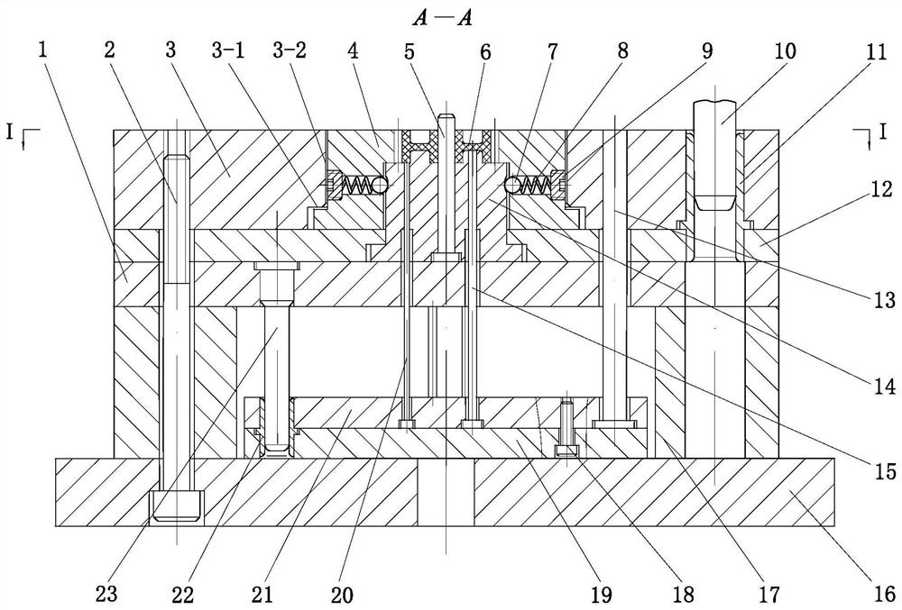
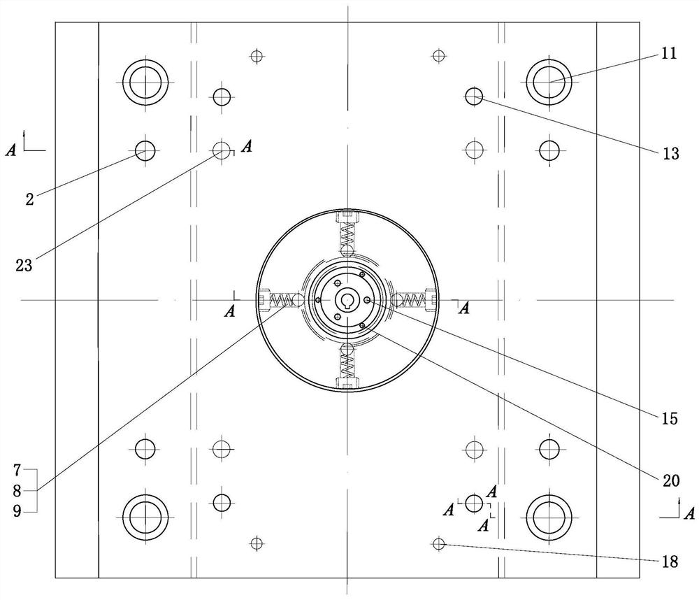
[0033] The structure of the present invention is as figure 1 and 2As shown, the device of the present invention is the main component of the movable mold in the injection molding mold for helical gear plastic parts, including the mold base (movable mold part), helical gear cavity insert, movable mold insert, core, ejector Components, launch mechanism. After the injection molding is completed, under the action of the mold opening mechanism of the injection machine, the movable mold part moves along the figure 1 The shown parting surface I-I retreats to the set position.

[0034] Push rod fixed plate 21, push plate 19, reset lever 13, push rod I15, push rod II20, push plate guide sleeve 22 and push plate guide post 23 form the push-out me...


PUM


Abstract

The invention discloses an ejector-assisted cavity rotating bevel wheel molded part stripping device and method. The device comprises a core fixing plate, a movable mold plate, a bevel wheel cavity insert, a movable mold insert, a core, an ejector assembly and a push-out mechanism, wherein the movable mold insert is arranged on the mold core fixing plate, the core is arranged on the movable mold insert, the bevel wheel cavity insert is arranged on the movable mold plate, and is fit on the movable mold insert, assembly gaps are reserved between the bevel wheel cavity insert and the movable moldplate and between the bevel wheel cavity insert and the movable mold insert, the ejector assembly is installed on the bevel wheel cavity insert, grooves are machined on the periphery of the outer side of the position, corresponding to the ejector assembly, of the movable mold insert, a central hole is formed in a bevel wheel molded part, the central hole is a circular hole with a square groove, and the core is a cylinder with a convex strip. According to the device, the bevel wheel molded part is separated and stripped from a bevel wheel cavity along the axial direction in the stripping process through the reverse stable and smooth rotation of the bevel wheel cavity, so that the effectiveness of stripping of the bevel wheel molded part is improved.

Description

technical field [0001] The invention relates to a demoulding device for a helical gear plastic part, in particular to a demoulding device and method for a helical gear plastic part in which an ejector assists the cavity rotation. Background technique [0002] In the process of mold opening and pick-up after injection molding of helical gear plastic parts, on the one hand, it is necessary to push out the gear plastic parts in a straight line along the mold opening direction under the action of the ejection mechanism; The corresponding rotational movement in the inclined direction of the tooth shape can realize the smooth demoulding of the helical gear plastic parts after forming. [0003] After searching, the existing public documents and patents all have corresponding solutions to the problem of ejection after injection molding of helical gear plastic parts, but there are still certain problems and deficiencies. Similar to Chinese Patent No. ZL201310733404.7, the applicatio...

Claims


Application Information

Patent Timeline
Patent Type & Authority Patents(China)
IPC IPC(8): B29C45/33B29C45/44
CPCB29C45/332B29C45/4435
Inventor 江昌勇江妦李丹虹姜伯军
Owner CHANGZHOU INST OF TECH
Learn More