High air tightness type air closer

An air-closing, high-air-tight technology, applied in conveyors, transportation and packaging, conveying bulk materials, etc., can solve the problems of limited area for installing sealing devices, and the sealing degree of rotating impellers cannot reach high air-tight conveying materials, etc. Achieving good dynamic sealing effect, increasing the area and reducing the diameter of the area

Pending Publication Date: 2019-11-01
MENGZHOU YUANHONG DRYING EQUIP RES & DEV CO LTD
View PDF0 Cites 0 Cited by
  • Summary
  • Abstract
  • Description
  • Claims
  • Application Information

AI Technical Summary

Problems solved by technology

[0002] At present, the air locker is suitable for the loading and unloading of dry powder and granular materials, and is used in the unloading devices of various mills, dryers, silos and other equipment; The requirements for performance and delivery pressure are getting higher and higher; the area of ​​the sealing device installed on the side plate of the rotating impeller of the air locker on the market and the top of the partition plate is limited, and the sealing degree of the rotating impeller cannot reach the high airtight conveying material when the rotating impeller rotates in and out of the material. , it is necessary to further innovate the design of the side plate, partition and sealing device of the rotating impeller of the air locker. High airtight sealing degree when rotating material in and out, reducing gas leakage

Method used


Image

  • High air tightness type air closer
  • High air tightness type air closer
  • High air tightness type air closer

Examples


Embodiment Construction

[0060] Below in conjunction with accompanying drawing and embodiment the invention is further described:

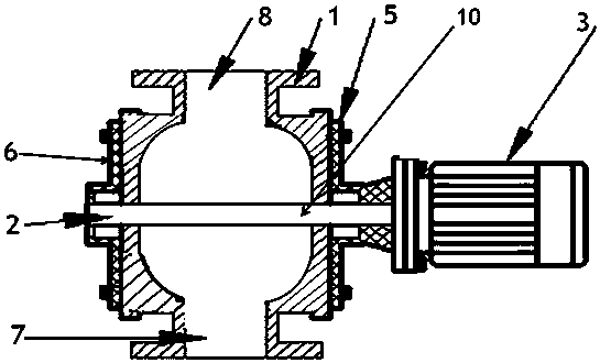
[0061] Such as figure 1 , figure 2 The shown high airtight air locker includes a valve body 1 , a rotating impeller 2 and a motor 3 .

[0062] The valve body 1 has a feed port 8 and a discharge port 7 up and down.

[0063] Both sides of described valve body 1 have front side cover 6, rear side cover 5.

[0064] The motor 3 is fixed on the rear side cover 5 of the valve body 1 .

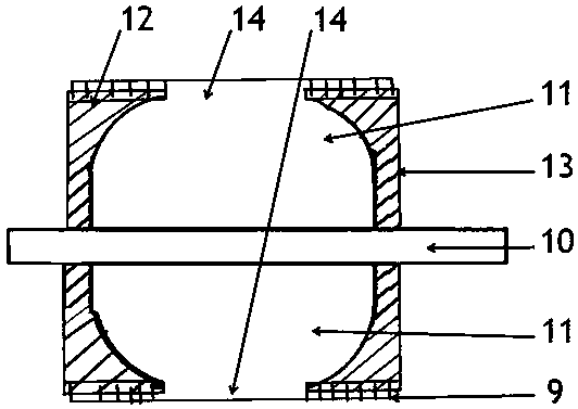
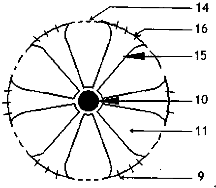
[0065] Such as figure 1 , figure 2 , image 3 The illustrated rotary impeller 2 includes a partition 15 , a sealing plate 12 , a side plate 13 , a drive shaft 10 , and a sealing device 9 .

[0066] The rotary impeller 2 is installed inside the valve body 1 .

[0067] One end of the transmission shaft 10 of the rotary impeller 2 is fixed in the bearing at the center position of the front side cover 6 , and the other end of the transmission shaft 10 passes through the bearing at the cente...


PUM


Abstract

The invention discloses a high air tightness type air closer. The high air tightness type air closer comprises a valve body, a rotating impeller and a motor, wherein the motor is fixed on a rear sidecover of the valve body; the rotating impeller is installed inside the valve body; a transmission shaft, extending out of the rear side cover of the valve body, of the rotating impeller is fixed on amotor shaft of the motor; a storage bin, consists of partition plates, a side plate and a sealing plate, positioned on the rotating impeller is provided with a small opening and a large middle part; and the aperture of the storage bin opening on the rotating impeller is reduced by the upper ends of the arc-shaped sectors of the partition plates and the sealing plate. The partition plates of the rotating impeller and a sealing device on the sealing plate are attached to a shell in the valve body, the attachment sealing area among the partition plates of the high-speed rotating impeller, the sealing device on the sealing plate and the shell in the valve body is large, the motor drives the transmission shaft of the rotating impeller to rotate, the better dynamic sealing effect of the sealingdevice can be achieved through the pressure buffering support of rubber and the sealing of hard materials, and the sealing air tightness of the dynamic sealing is high when the rotating impeller rotates; and the air closer is strong in practicability and wide in application range.

Description

technical field [0001] The invention relates to an air locker, in particular to a highly airtight type air locker. Background technique [0002] At present, the air locker is suitable for the loading and unloading of dry powder and granular materials, and is used in the unloading devices of various mills, dryers, silos and other equipment; The requirements for performance and delivery pressure are getting higher and higher; the area of ​​the sealing device installed on the side plate of the rotating impeller of the air locker on the market and the top of the partition plate is limited, and the sealing degree of the rotating impeller cannot reach the high airtight conveying material when the rotating impeller rotates in and out of the material. , it is necessary to further innovate the design of the side plate, partition and sealing device of the rotating impeller of the air locker. The high airtight sealing degree when the material is rotated in and out reduces the leakage ...

Claims


Application Information

Patent Timeline
Patent Type & Authority Applications(China)
IPC IPC(8): B65G53/46
CPCB65G53/4625
Inventor 程长青代爱妮郭银浦
Owner MENGZHOU YUANHONG DRYING EQUIP RES & DEV CO LTD
Why Eureka
Try Eureka