
Integrated air conditioner

An integrated, air-conditioning technology, which is applied in the direction of air-conditioning systems, heating methods, high-efficiency regulation technology, etc., can solve the problems of increased energy consumption, non-movability, inconvenient installation, etc., and achieve the effect of improving cooling efficiency

Inactive Publication Date: 2019-11-01
SHENYANG WONDERFUL TECH
View PDF0 Cites 0 Cited by
  • Summary
  • Abstract
  • Description
  • Claims
  • Application Information

AI Technical Summary

Problems solved by technology

The main problems in the application process of the split air conditioner include: this split air conditioner is divided into internal and external units, and the condenser inside the external unit needs to dissipate heat to the outside, so it needs to be installed outdoors regardless of the cooling capacity. The copper pipes and control cables connecting the indoor and outdoor units cause the current installation inconvenience; moreover, since the air conditioner inner unit needs to be connected to a fixed outdoor unit, it cannot be moved after installation. If it needs to be moved, professional air conditioner maintenance personnel are required Carry out dismantling and relocation, and at the same time have a high failure rate, which brings inconvenience to relocation
Since the air conditioner is installed inside the room, the installation location is often not the closest to the heat source, and it is necessary to cool the entire room to achieve the effect of cooling the cabinet; the space volume of a small computer room is often several times the volume of the actual cabinet, so the operation is bound to increase greatly. energy consumption; in order to improve the cooling effect and efficiency of the air conditioner, it is often necessary to set up special air ducts for the insulation layer at the bottom of the floor and the ceiling frame, and arrange the inlet and outlet air near the inner cabinet group to form an upper and lower return air loop, increasing Construction Difficulty and Cost

Method used


Image

  • Integrated air conditioner
  • Integrated air conditioner
  • Integrated air conditioner

Examples


Embodiment Construction

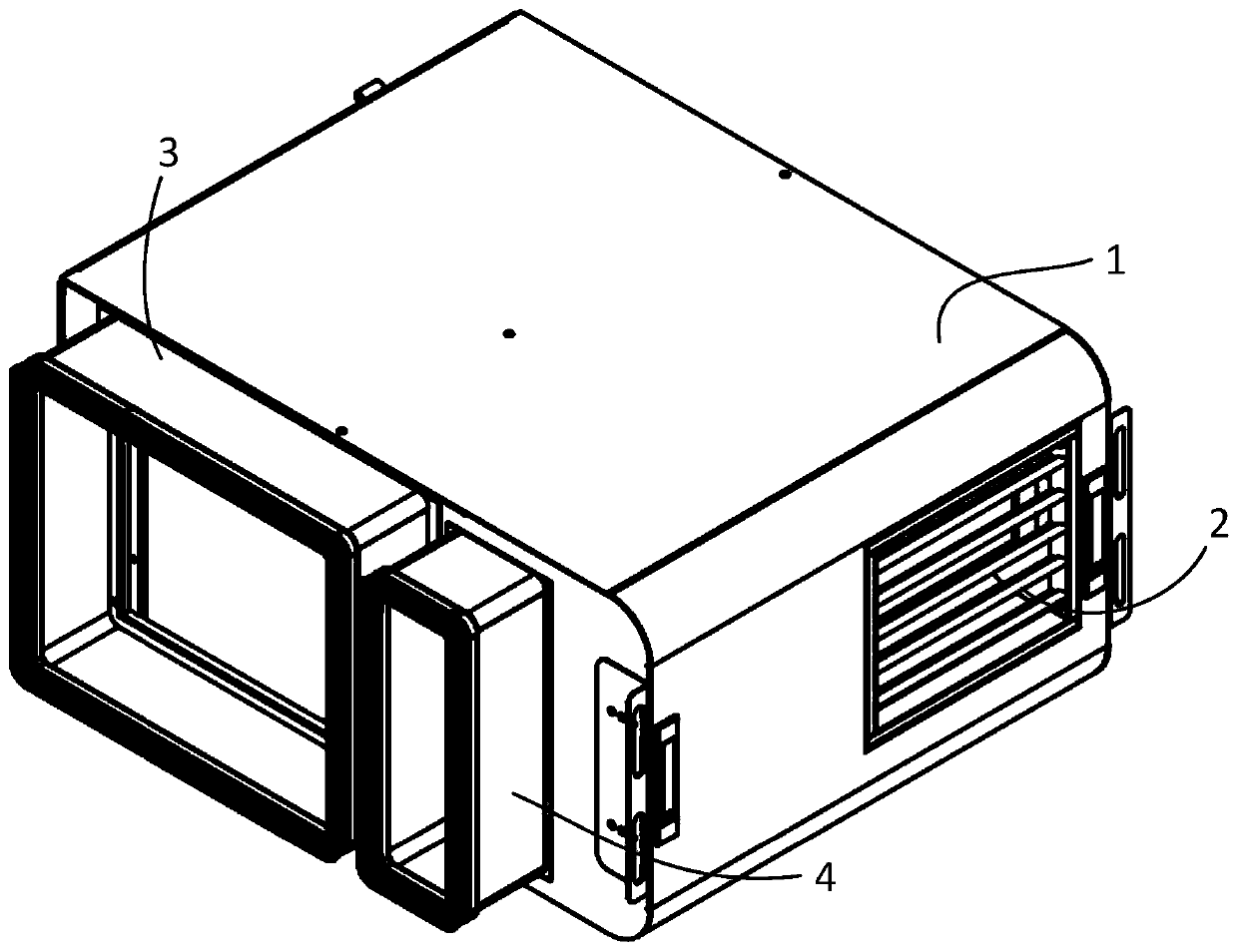
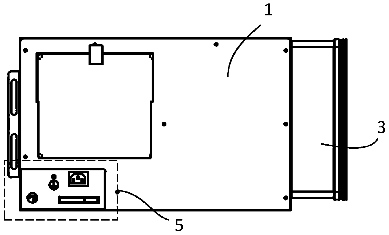
[0054] In order to solve the problems in the prior art, the present invention provides an integrated air conditioner, which does not have an indoor unit and an outdoor unit, but is integrated, so it can overcome many disadvantages caused by the split air conditioner. Thereby it is more suitable for practical use.

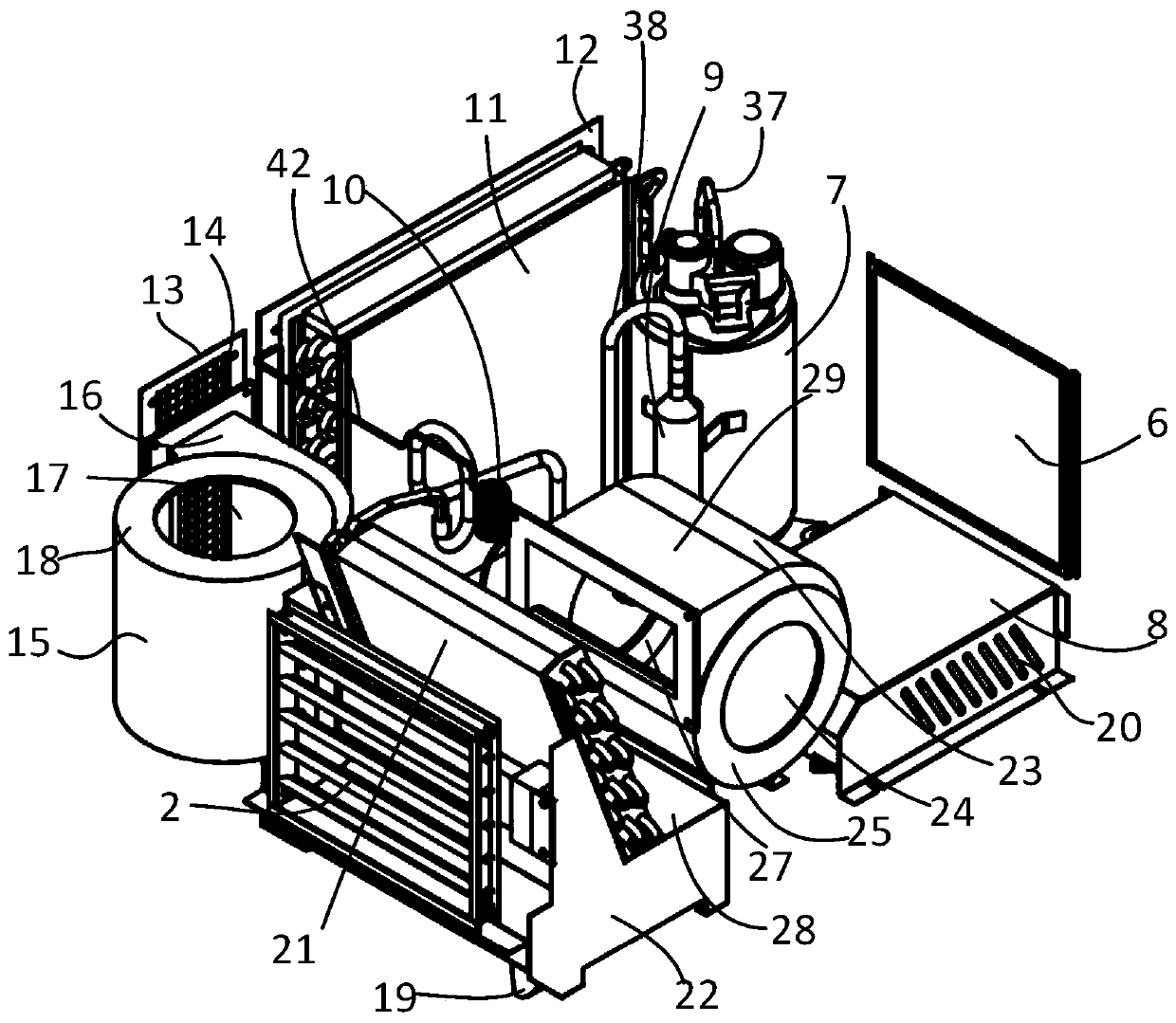
[0055] In order to further explain the technical means and effects of the present invention to achieve the intended purpose of the invention, the specific implementation, structure, features and effects of the integrated air conditioner proposed according to the present invention will be described below in conjunction with the accompanying drawings and preferred embodiments. , as detailed below. In the following description, different "an embodiment" or "an embodiment" do not necessarily refer to the same embodiment. Furthermore, the features, structures, or characteristics of one or more embodiments may be combined in any suitable manner.

[0056] The term "and / o...


PUM


Abstract

The invention discloses an integrated air conditioner, and belongs to the technical field of air conditioners. According to the integrated air conditioner, an evaporator, a condenser, a compressor, aheating body, a first fan, a second fan, a water collecting disc, a drain pipe, an air outlet grid, an air return pipe and a capillary pipe are arranged inside a shell; a water outlet of the drain pipe is formed in the outside of the shell; a first outer circulation channel and a second outer circulation channel are further arranged on the shell; an air outlet of the second fan is aligned with thefirst outer circulation channel; the condenser is aligned with the second outer circulation channel; and the air outlet grid is arranged on one side surface of the shell and aligned with an air outlet of a fan. The integrated air conditioner is integrated without an indoor unit and an outdoor unit, so that a plurality of disadvantages brought by a split air conditioner are overcome.

Description

technical field [0001] The invention relates to the technical field of air conditioners, in particular to an integrated air conditioner. Background technique [0002] Air conditioners in the prior art are usually of a split type, including an air conditioner indoor unit and an air conditioner outdoor unit, wherein the outdoor unit is fixed outdoors and connected to the indoor unit through electric control cables and copper pipes; the indoor unit is installed in a room outside the cabinet , by cooling the entire room to achieve the purpose of cooling or heating the cabinet. In the process of applying this type of air conditioner, it is usually necessary to set up special hot and cold air passages to achieve the preset cooling effect. The main problems in the application process of the split air conditioner include: this split air conditioner is divided into internal and external units, and the condenser inside the external unit needs to dissipate heat to the outside, so it n...

Claims


Application Information

Patent Timeline
IPC IPC(8): F24F1/022F24F1/0323F24F11/38F24F11/61F24F11/77F24F11/86F24F11/88F24F13/08F24F13/22F24F13/30F24F110/10
CPCF24F1/022F24F1/0323F24F11/38F24F11/61F24F11/77F24F11/86F24F11/88F24F13/082F24F13/222F24F13/30F24F2110/10Y02B30/70
Inventor 李春寒蔡增侯涛徐刚
Owner SHENYANG WONDERFUL TECH
Learn More