Visualized fuel cell device

A fuel cell and collector plate technology, applied in the direction of fuel cells, fuel cell control, fuel cell additives, etc., can solve the problem that the side of the flow channel cannot be visualized, and achieve the effect of low cost and simple processing and production

Pending Publication Date: 2019-11-01
TSINGHUA UNIV
View PDF3 Cites 6 Cited by
  • Summary
  • Abstract
  • Description
  • Claims
  • Application Information

AI Technical Summary

Problems solved by technology

[0006] In order to at least solve the problem that the flow channel side cannot be visualized in the prior art, the present invention provides a visual fuel cell device, which includes: a cathode flow field unit, the cathode flow field unit is conductive; MEA membrane electrode, the The upper surface of the MEA is attached to the bottom surface of the cathode flow field unit; and the anode flow field uni

Method used


Image

  • Visualized fuel cell device
  • Visualized fuel cell device
  • Visualized fuel cell device

Examples


Embodiment Construction

[0027] In order to make the object, technical solution and advantages of the present invention clearer, the implementation manner of the present invention will be further described in detail below in conjunction with the accompanying drawings.

[0028] The present invention will be described in detail below with reference to the accompanying drawings and examples. Each example is provided by way of explanation of the invention, not limitation of the invention. In fact, those skilled in the art will recognize that modifications and variations can be made in the present invention without departing from the scope or spirit of the invention. For example, features illustrated or described as part of one embodiment can be used on another embodiment to yield a still further embodiment. Therefore, it is intended that the present invention includes such modifications and variations as come within the scope of the appended claims and their equivalents.

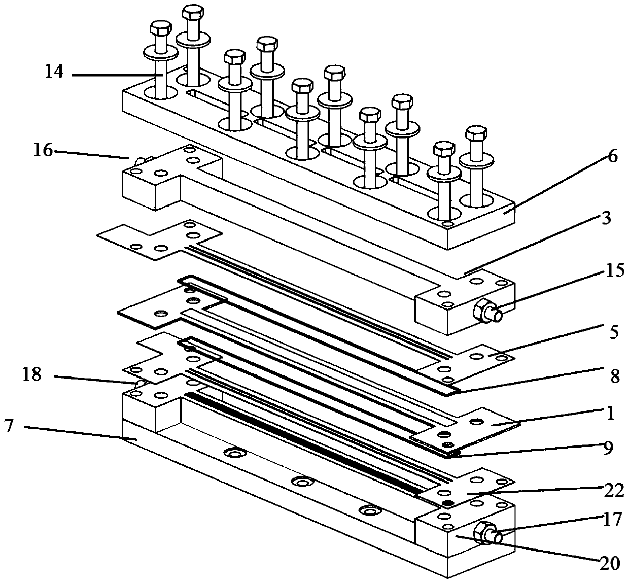
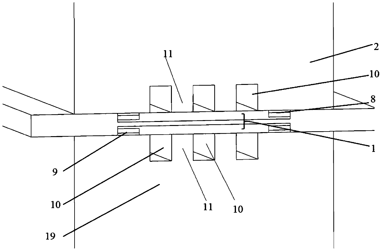
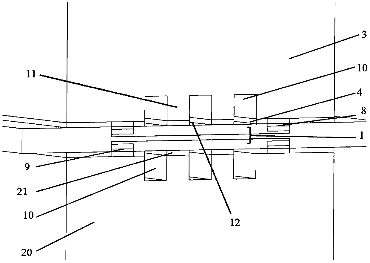
[0029] see Figure 1~4 , an e...


PUM


Abstract

The invention belongs to the field of fuel cells, and discloses a visualized fuel cell device. The visualized fuel cell device comprises a cathode flow field unit, the cathode flow field unit is conductive; an MEA membrane electrode, wherein the upper surface of the MEA is laminated with the bottom surface of the cathode flow field unit; and an anode flow field unit, wherein the top surface of theanode flow field unit is laminated with the lower surface of the MEA, the anode flow field unit is conductive, at least one of the anode flow field unit and the cathode flow field unit is transparent, and the top surface of the anode flow field unit and the bottom surface o the cathode flow field unit are respectively provided with grooves to form a flow path and form a ridge. The flow path is atransparent flow path by arranging at least one of the anode flow field unit and the cathode flow field unit to be transparent, a high-speed camera equipped with a microscope head is adopted to alignwith an area to be shot to achieve the visualization of the top portion or the bottom portion and the side of the flow path and achieve the visualization of the flow state and the distribution of twophase flows in the fuel cell.

Description

technical field [0001] The invention belongs to the technical field of fuel cells, in particular to a visualized fuel cell device. Background technique [0002] Proton exchange membrane fuel cells have the advantages of low operating temperature, high efficiency, and environmental protection, and are an important part of the future vehicle power system. However, due to the water management problem of proton exchange membrane fuel cells, further improvement of its durability and performance is restricted. Especially under high current density conditions, a large amount of water, the product of the electrochemical reaction, will be produced. If the water cannot be discharged quickly at this time, it will block the flow channel and the pores of the diffusion layer, causing the reaction gas to fail to reach the reaction interface to react and flow channel Increased resistance and other issues. [0003] The fuel cell visualization device is a low-cost, intuitive observation dev...

Claims


Application Information

Patent Timeline
IPC IPC(8): H01M8/0221H01M8/0239H01M8/0206H01M8/0232H01M8/0258H01M8/04298H01M8/0276H01M8/0271
CPCH01M8/0206H01M8/0221H01M8/0232H01M8/0239H01M8/0258H01M8/0271H01M8/0276H01M8/04305Y02E60/50
Inventor 杨家培马骁张晓卿帅石金
Owner TSINGHUA UNIV
Why Eureka
Try Eureka