
Brake system-used brushless motor rotor punching sheet structure

A technology for rotor punching and brushless motors, which is applied in the field of permanent magnet synchronous motor rotor punching structure, which can solve the problems of irreversible demagnetization of magnetic steel, magnetic saturation, and affecting the dynamic performance of permanent magnet synchronous motors, and achieve enhanced magnetic isolation effect , Increase the effect of quadrature axis equivalent reluctance

Pending Publication Date: 2019-11-01
NIDEC KAIYU AUTO ELECTRIC JIANGSU
View PDF2 Cites 2 Cited by
  • Summary
  • Abstract
  • Description
  • Claims
  • Application Information

AI Technical Summary

Problems solved by technology

[0002] The AC-D axis coupling of permanent magnet synchronous motor is a very complicated problem. The magnetization process may cause magnetic saturation, and the demagnetization process may cause irreversible demagnetization of the magnet steel, thereby affecting the dynamic performance of the permanent magnet synchronous motor. The application number is 201510329694.8 A patent for the invention of the rotor punching structure of a permanent magnet servo motor discloses a punching structure: the rotor punching body above the permanent magnet slot is provided with magnetic isolation holes arranged in parallel, but such magnetic isolation holes may Intersect with the direction of the magnetic field line, block the cross-axis magnetic circuit and block the main magnetic field path at the same time, resulting in a decrease in the power density of the motor
Another punching structure is disclosed in the invention patent of a rotor punching sheet of a motor with the application number 201520419702.3: the rotor punching body above the permanent magnet slot is provided with magnetic isolation holes arranged at an angle, and the same magnetic isolation The hole may also cross the direction of the magnetic force line, blocking the cross-axis magnetic circuit and also blocking the main magnetic field path, resulting in a decrease in the power density of the motor

Method used


Image

  • Brake system-used brushless motor rotor punching sheet structure
  • Brake system-used brushless motor rotor punching sheet structure
  • Brake system-used brushless motor rotor punching sheet structure

Examples


Embodiment Construction

[0020] The following will clearly and completely describe the technical solutions in the embodiments of the present invention with reference to the accompanying drawings in the embodiments of the present invention. Obviously, the described embodiments are only some, not all, embodiments of the present invention.

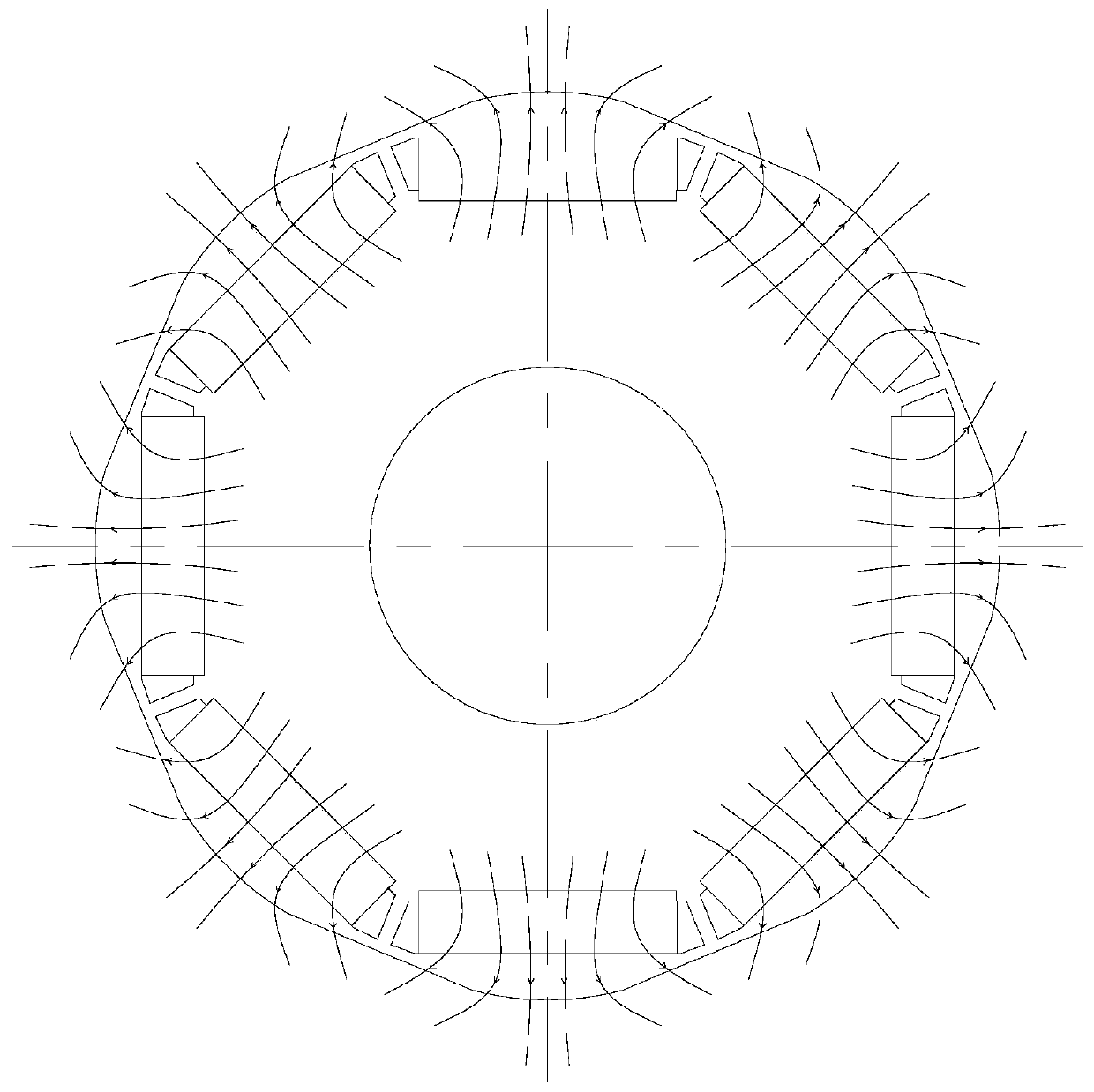
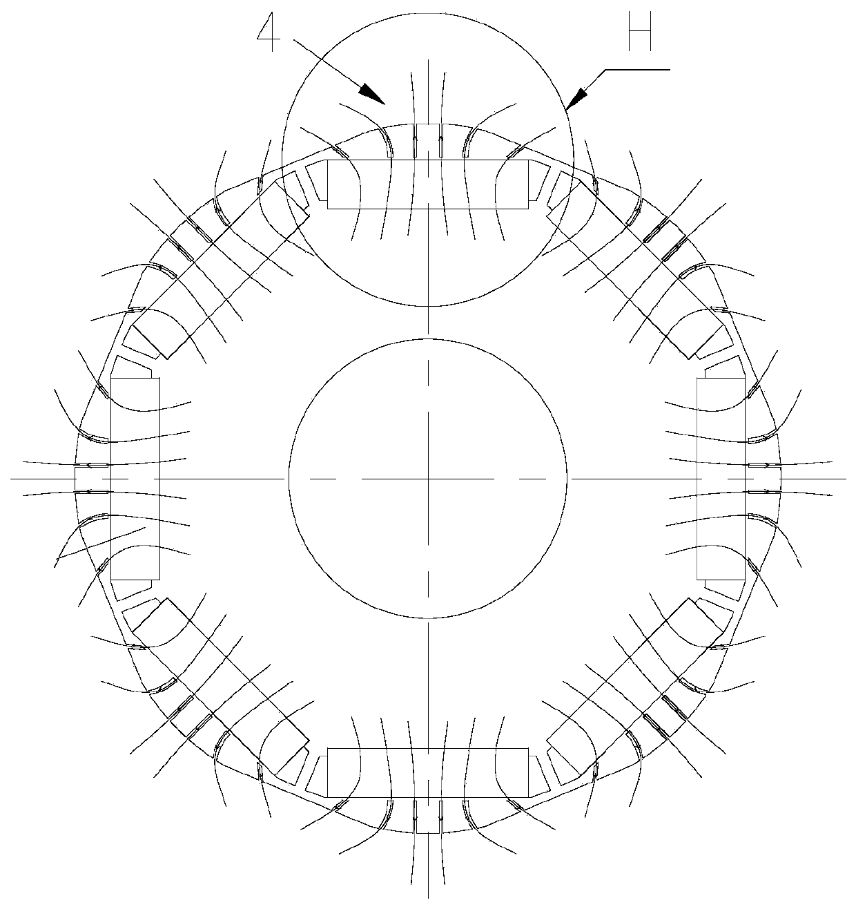
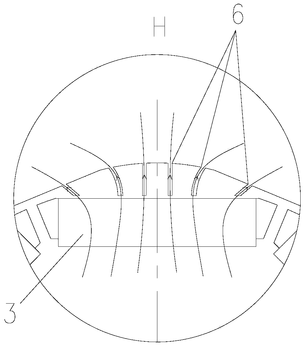
[0021] refer to Figure 1-5 , a rotor stamping structure for a brushless motor for a brake system, including a rotor stamping 1, the center of the rotor stamping 1 has a shaft groove 2, and the rotor stamping 1 is located on the outer periphery of the shaft groove 2 and is evenly provided with several along the circumferential direction. The magnetic steel groove 3, the outer edge of the rotor punching piece 1 is located at each magnetic steel groove 3 with a magnetic separation groove 4, the angle between the center line of the magnetic separation groove 4 and the magnetic force line of the rotor punching piece 1 is 0°, and the separation There is a magnetic isolati...


PUM


Abstract

The invention discloses a brake system-used brushless motor rotor punching sheet structure, which comprises a rotor punching sheet. The circle center of the rotor punching sheet is provided with a rotating shaft groove; the periphery of the rotating shaft groove of the rotor punching sheet is uniformly provided with a plurality of magnetic steel grooves along a circumferential direction; a magnetic isolation groove is arranged at each magnetic steel groove and at the outer edge of the rotor punching sheet; the included angle between the center line of the magnetic isolation groove and the magnetic line of the rotor punching piece is 0 DEG; and a magnetic isolation filling block is arranged in the magnetic isolation groove. The a-axis equivalent reluctance of the motor can be increased, andthe brake system-used permanent magnet brushless motor parameter nonlinear influences caused by cross coupling of d-axis and a-axis magnetic circuits can be reduced.

Description

technical field [0001] The invention relates to a stamping structure of a rotor of a permanent magnet synchronous motor. Background technique [0002] The AC-D axis coupling of permanent magnet synchronous motor is a very complicated problem. The magnetization process may cause magnetic saturation, and the demagnetization process may cause irreversible demagnetization of the magnet steel, thereby affecting the dynamic performance of the permanent magnet synchronous motor. The application number is 201510329694.8 A patent for the invention of the rotor punching structure of a permanent magnet servo motor discloses a punching structure: the rotor punching body above the permanent magnet slot is provided with magnetic isolation holes arranged in parallel, but such magnetic isolation holes may Intersect with the direction of the magnetic force line, block the quadrature axis magnetic circuit and also block the main magnetic field path, resulting in a decrease in the power densit...

Claims


Application Information

Patent Timeline
Patent Type & Authority Applications(China)
IPC IPC(8): H02K1/27
CPCH02K1/27H02K2213/03
Inventor 王咏涛邱高峰王朝海
Owner NIDEC KAIYU AUTO ELECTRIC JIANGSU
Learn More