

Plasma waste gas processing device
A waste gas treatment equipment, plasma technology, applied in gas treatment, separation method, dispersed particle separation, etc., can solve the problem of inability to filter dust and shock absorption effect, and achieve the effect of improving filtering effect, good shock absorption and buffering effect, and reducing noise.
- Summary
- Abstract
- Description
- Claims
- Application Information
AI Technical Summary
Problems solved by technology
Method used
Image

Examples
Embodiment
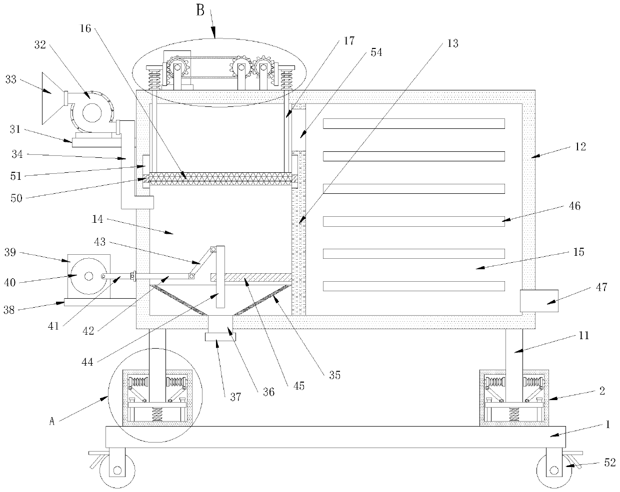
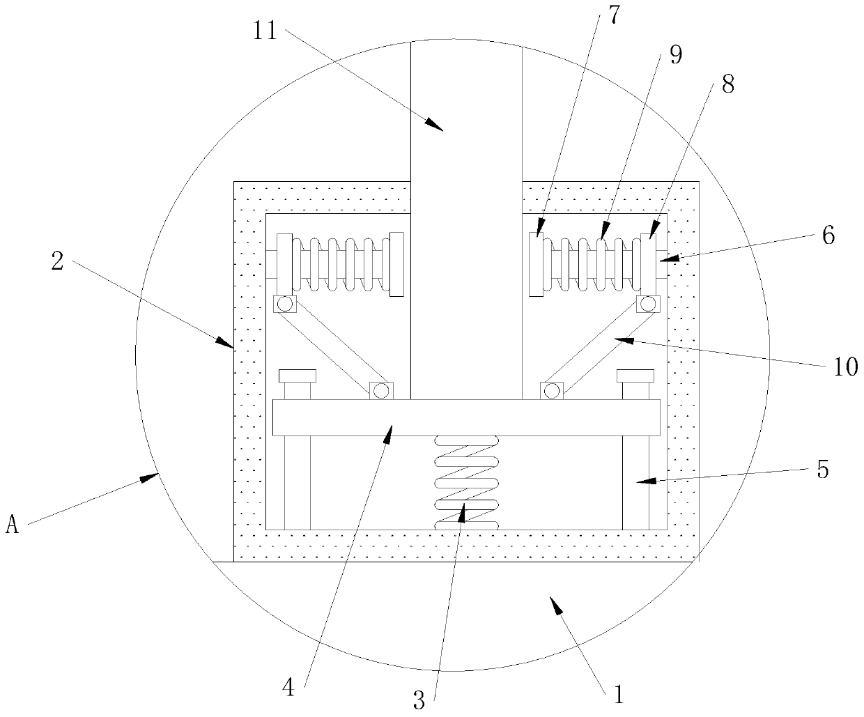
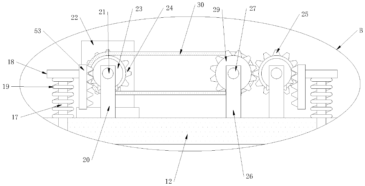
[0030] see Figure 1-7, the present invention provides the following technical solutions: a plasma exhaust gas treatment equipment, including a base 1, the top four corners of the base 1 are fixed with a box 2, the bottom inner wall of the box 2 is fixed with a first spring 3, the first spring 3 The top is fixed with a support plate 4, the bottom inner wall of the box body 2 is symmetrically fixed with a vertical bar 5, the support plate 4 is slidably connected to the outer side wall of the vertical bar 5, and the inner wall of both sides of the box body 2 is fixed with a horizontal bar 6. One end of the bar 6 is fixed with a fixed plate 7, and the outer wall of the cross bar 6 is slidably connected with a slide plate 8, and the outer side of the cross bar 6 is provided with a second spring 9, and the two ends of the second spring 9 are respectively fixed with the adjacent The side walls of the plate 7 and the slide plate 8 are fixedly connected, and the bottom of the slide pl...
PUM
 Abstract
Description
Claims
Application Information