
Spinning dust collecting mechanism for spinning machine

A technology of machine spinning dust and collecting mechanism, applied in the field of textile machinery, can solve the problems of wasting workers' time, large loss of textile machines, adsorption of textile dust, etc., and achieve the effects of avoiding falling, saving energy, and increasing adsorption.

Inactive Publication Date: 2019-11-05
温州浩僧服饰有限公司
View PDF7 Cites 11 Cited by
  • Summary
  • Abstract
  • Description
  • Claims
  • Application Information

AI Technical Summary

Problems solved by technology

[0003] The existing textile machines will raise dust when they are working. These dusts are harmful to people and have a high loss to the textile machines. They need to be removed. At present, most of the existing textile dust removal methods are removed by vacuum cleaners. Cotton lint in the textile dust is easy to adhere to the vacuum cleaner. After a period of adsorption, manpower is required to clean up the textile dust in the vacuum cleaner. This wastes the time of the workers and the cleaned textile dust is easy to escape and cause health hazards to the workers. Moreover, the vacuum cleaner The textile dust inside the textile machine cannot be well adsorbed, and the adsorption effect is not ideal. For the long-term normal operation of the textile machine, the heat dissipation effect is not good and the textile dust is easily attached to the parts in the textile machine. Greater loss

Method used


Image

  • Spinning dust collecting mechanism for spinning machine
  • Spinning dust collecting mechanism for spinning machine
  • Spinning dust collecting mechanism for spinning machine

Examples


Embodiment Construction

[0024] In order to make the above objects, features and advantages of the present invention more comprehensible, specific implementations of the present invention will be described in detail below in conjunction with the accompanying drawings. In the following description, numerous specific details are set forth in order to provide a thorough understanding of the present invention. However, the present invention can be implemented in many other ways different from those described here, and those skilled in the art can make similar improvements without departing from the connotation of the present invention, so the present invention is not limited by the specific implementations disclosed below.

[0025] It should be noted that when an element is referred to as being “fixed” to another element, it can be directly on the other element or there can also be an intervening element. When an element is referred to as being "connected to" another element, it can be directly connected ...


PUM


Abstract

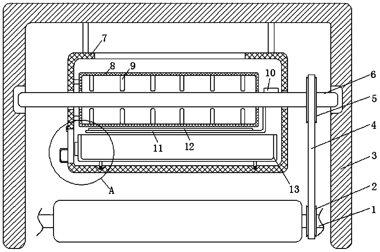
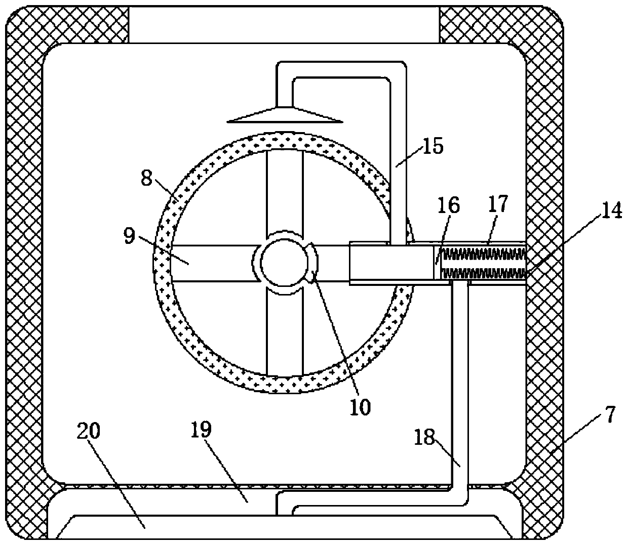
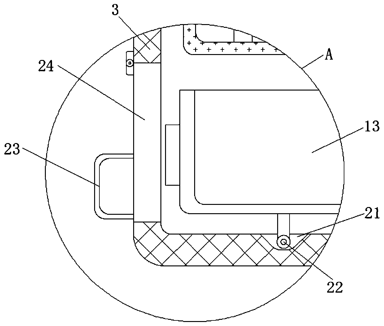
The invention discloses a spinning dust collecting mechanism for a spinning machine. The spinning dust collecting mechanism comprises a driving roll for driving the spinning machine to act and a housing mounted on the spinning machine, wherein the housing, relative to the inner wall, is rotatably connected with a rotating shaft; a dust collecting chamber is rotatably arranged on the rotating shaftin a sleeving mode; the inner wall of the dust collecting chamber is fixedly connected with a static cylinder arranged on the rotating shaft through a connecting column in the sleeving mode; and an adsorption device for adsorbing spinning dust is mounted inside the static cylinder. In the invention, the rotating shaft rotates to drive fur to rub with an arc-shaped block to generate electricity, the spinning dust is adsorbed through the static cylinder, a magnet connected with the side wall of the rotating shaft is attracted with a magnetic sliding plug inside a sleeve fixedly connected with the side wall of the dust collecting chamber oppositely, negative pressure is generated constantly inside the sleeve for constantly recycling spinning dust in the constant rotating process of the rotating process, the adsorption for spinning dust is strengthened, the surface of the static cylinder is cleaned by an elastic scraper plate in the rotating process of the rotating shaft, and the condition that much dust is adsorbed onto the static cylinder due to untimely cleaning to influence the adsorption effect is avoided.

Description

technical field [0001] The invention relates to the technical field of textile machinery, in particular to a textile dust collection mechanism of a textile machine. Background technique [0002] Textile machine is the full name of the tool that processes thread, silk, hemp and other raw materials into silk thread and then weaves it into cloth, including spinning pendant, spinning wheel, spindle, pedal loom, modern mechanical loom, modern numerical control automatic loom, etc. The development of ancient and modern textile processes and equipment is designed in response to textile raw materials. Therefore, raw materials play an important role in textile technology. The fibers used for weaving in various countries in the ancient world are all natural fibers, generally three short fibers (wool, hemp, and cotton). [0003] Existing textile machines will raise dust when they are working. These dusts are harmful to people and have a high loss to the textile machines. They need to ...

Claims


Application Information

Patent Timeline
IPC IPC(8): B03C3/28B03C3/74B08B15/00
CPCB03C3/28B03C3/743B08B15/00
Inventor 王松
Owner 温州浩僧服饰有限公司
Learn More