Roller reciprocating driving mechanism of high-speed cold pipe mill

A cold rolling mill, reciprocating drive technology, applied in the direction of the drive device for metal rolling mills, metal rolling, metal rolling, etc., can solve the problem of affecting product quality and equipment life, limited balance weight, poor balance effect, etc. Problems, to achieve the effect of weight reduction, improvement of finished product quality pass rate, processing difficulty and processing cost reduction

Pending Publication Date: 2019-11-05
张家港恒立机械有限公司
View PDF0 Cites 2 Cited by
  • Summary
  • Abstract
  • Description
  • Claims
  • Application Information

AI Technical Summary

Problems solved by technology

[0002] In the rolling process of the existing cold-rolled pipe mill, the work roll seat generates inertial force due to reciprocating motion, and the inertial force is transmitted to the main frame, which causes the vibration of the main frame, which in turn causes the loosening of the equipment foundation and affects the quality of the product. Quality and Equipment Life
[0003] In the prior art, the roll seat is driven by a single transmission gear. Since the balance weight that can be configured by the transmission gear is limited, although its manufacturing cost is relatively low, the balance effect is not good.

Method used


Image

  • Roller reciprocating driving mechanism of high-speed cold pipe mill

Examples


Embodiment Construction

[0018] Specific embodiments of the present invention will be described in detail below in conjunction with the accompanying drawings.

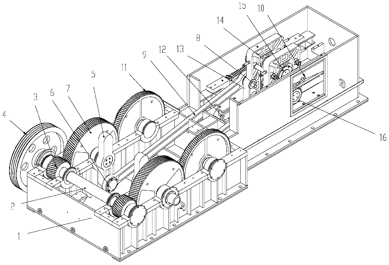
[0019] like figure 1 As shown, a roll reciprocating drive mechanism of a high-speed cold-rolled pipe mill includes a main frame 1, and one end of the main frame 1 is horizontally provided with a drive shaft 2, and a pair of drive gears 3 are symmetrically distributed on the drive shaft 2, and one end of the drive shaft 2 is fixedly arranged. Pulley 4 is arranged. The drive gear 3 on the drive shaft 2 near the pulley 4 side is connected to the drive shaft 2 through a double key to transmit torque, and the other drive gear 3 is connected to the drive shaft 2 through a shrink sleeve to transmit torque.

[0020] Both sides of the main base 1 are respectively provided with two transmission gears 7 meshed with the drive gear 3, and the inner end of the gear shaft of the transmission gear 7 is provided with a link arm 5. The joint of the gear shaft...


PUM


Abstract

The invention discloses a roller reciprocating driving mechanism of a high-speed cold pipe mill. The roller reciprocating driving mechanism of the high-speed cold pipe mill comprises a main machine seat; a driving shaft is horizontally arranged at one end of the main machine seat; a pair of driving gears are symmetrically distributed on the driving shaft; a belt pulley is fixedly arranged at one end of the driving shaft; two sides of the main machine seat are respectively provided with two transmission gears engaged with the driving gears; the inner ends of gear shafts of the transmission gears are provided with connecting rod arms, mounting long grooves are formed in the connecting rod arms; one ends of the connecting rods are movably connected with the connecting rod arms through movablerods movably embedded in the mounting long grooves; fan-shaped notches are symmetrically formed in the positions, on two sides of the portion where the connecting rod arms are provided with the mounting long grooves, of the transmission gears; balance gears engaged with the transmission gears are arranged at the positions, on one side, away from the driving shaft, of the transmission gears, of the main machine seat; fan-shaped inner concaves are formed in the balance gears; a group of linear guide rails are arranged at the bottom of the other end in the main machine seat in parallel; a rollerseat is arranged on the linear guide rails; and two sides of the front end of the roller seat are movably connected with the other ends of the connecting rods through connecting shafts.

Description

technical field [0001] The invention relates to the field of cold-rolled pipe mills, in particular to a roll reciprocating drive mechanism of a high-speed cold-rolled pipe mill. Background technique [0002] In the rolling process of the existing cold-rolled pipe mill, the work roll seat generates inertial force due to reciprocating motion, and the inertial force is transmitted to the main frame, which causes the vibration of the main frame, which in turn causes the loosening of the equipment foundation and affects the quality of the product. quality and equipment life. [0003] In the prior art, the roll seat is driven by a single transmission gear. Since the balance weight that the transmission gear can configure is limited, although its manufacturing cost is relatively low, the balance effect is not good. Contents of the invention [0004] The technical problem to be solved by the present invention is to provide a roll reciprocating drive mechanism of a high-speed cold...

Claims


Application Information

Patent Timeline
Patent Type & Authority Applications(China)
IPC IPC(8): B21B35/12
CPCB21B35/12
Inventor 严红夏王惠新
Owner 张家港恒立机械有限公司
Why Eureka
Try Eureka