
hydraulic cylinder piston

A technology of cylinder piston and hydraulic cylinder, applied in the direction of fluid pressure actuating device, etc., can solve the problems of increasing the difficulty of hydraulic cylinder or cylinder control circuit design, inability to eliminate shock vibration and noise, and affecting the buffer effect, etc. Reliable work and good buffering effect

Active Publication Date: 2016-03-23
SICHUAN ENG TECHN COLLEGE
View PDF6 Cites 2 Cited by
  • Summary
  • Abstract
  • Description
  • Claims
  • Application Information

AI Technical Summary

Problems solved by technology

One is set on the control circuit outside the cylinder body, which has defects such as complex structure, large volume, troublesome manufacturing, and high manufacturing cost
The other is to be arranged on the piston inside the cylinder. This arrangement is either to use the working medium in the cylinder to directly buffer the operation of the piston. CN203161708, publication date: August 28, 2013), "buffer hydraulic cylinder" (publication number: CN203374549, publication date: January 1, 2014); or use elastic parts to buffer the piston, such as Chinese patent documents The disclosed "two-way automatic buffer hydraulic cylinder" (publication number: CN202768523, publication date: March 6, 2013); although they have the advantages of simple structure, small size, convenient manufacture, and low manufacturing cost, they are practical And the problem of poor reliability, this is because: using the working medium in the cylinder to directly buffer the piston operation, it is necessary to ensure that a certain amount of working medium is reserved in the cylinder, and too much working medium will effectively improve the buffering effect , otherwise it will affect the buffering effect, thus increasing the design difficulty of the hydraulic cylinder or cylinder control circuit, the operability is poor, and it is not practical; The direct mechanical collision of the end cover, but the elastic part is always in repeated contact and collision with the cylinder bottom or the end cover of the cylinder during the reciprocating movement of the piston. This contact collision will not damage the cylinder in a short period of time, but the shock vibration and Noise is always irreversible, poor reliability

Method used


Image

  • hydraulic cylinder piston
  • hydraulic cylinder piston
  • hydraulic cylinder piston

Examples


Embodiment 1

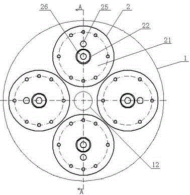
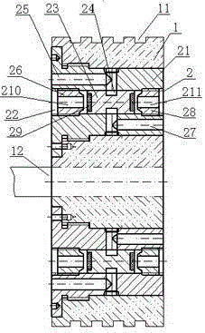
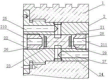
[0022] See figure 1 , figure 2 with image 3 : The present invention includes a piston body 1 and a buffer mechanism 2 arranged on the piston body 1 to relieve pressure.

[0023] Among them, the piston body 1 is a cylindrical structure with a certain thickness, and its thickness and diameter are reasonably determined according to the performance of the applied hydraulic cylinder. On the circumference of the piston body 1, there are four annular sealing grooves 11 filled with sealing rings. The number of the sealing grooves 11 is also reasonably determined according to the performance of the hydraulic cylinder, such as two, three, etc., which are mainly used to prevent During the working process of the hydraulic cylinder, the hydraulic oil leaks freely from the high pressure chamber (that is, the pressure side of the piston) to the low pressure chamber (that is, the pressure discharge side of the piston). A piston rod 12 is connected to the aforementioned piston body 1, and the p...

Embodiment 2

[0031] The other structure of this embodiment is the same as that of the first embodiment, the difference is that: the buffer housing and the piston body constituting the buffer mechanism are an integrated structure, that is, the piston body itself also serves as the buffer housing, in a predetermined position of the piston body (that is, The position for assembling the buffer mechanism in embodiment 1) is provided with an axial through-hole-shaped pressure relief hole, two end hole wall sections of the pressure relief hole are provided with connecting threads, and the piston near the pressure relief hole The left end surface of the body is provided with a first diversion hole leading to the middle of the pressure relief hole, and the right end surface is provided with a second diversion hole leading to the middle of the pressure relief hole. The pressure relief hole and the diversion hole (that is, the first diversion hole and the second diversion hole) provided on the piston b...


PUM


Abstract

The invention discloses a hydraulic cylinder piston, which includes a piston body provided with at least one buffer mechanism; the buffer mechanism is mainly composed of a buffer housing arranged in the piston body, a pressure relief valve, and first and second screw plugs , the buffer shell is provided with a pressure relief hole, and the left and right end faces of the buffer shell are respectively provided with diversion holes leading to the inside of the pressure relief hole, the two diversion holes in the pressure relief hole correspond to each other, and the pressure relief There is an annular pressure relief groove on the middle circumference of the valve, which is assembled in the pressure relief hole. The width of the pressure relief groove corresponds to the diameter of the diversion hole in the pressure relief hole. The first and second screw plugs are respectively provided with pressure introduction holes. The first and second screw plugs are assembled at both ends of the pressure relief hole, the diversion hole and the pressure relief valve in the pressure relief hole are between the first and second screw plugs, and the gap between the first and second screw plugs is The pressure relief hole forms the reciprocating space of the pressure relief valve, and when the pressure relief valve is at the stroke end in the reciprocating space, the pressure relief groove is blocked. Under load, it decelerates to zero when it reaches the end of the stroke, and works reliably.

Description

technical field [0001] The present invention relates to a reciprocating piston in a hydraulic cylinder or cylinder. Background technique [0002] When the hydraulic cylinder or cylinder is working, the piston in the cylinder runs at a high speed under the action of the working medium (hydraulic oil or compressed air), so the inertial force of the piston is relatively large (this is especially the case with large-mass pistons. ), causing the piston to form a large impact load at the end of the stroke, and mechanically collide with the cylinder bottom or end cover of the cylinder block, which not only causes shock vibration and noise, but also easily damages the cylinder block (usually loosening or even knocking down the cylinder block) body end cap or cylinder bottom). Therefore, it is essential to design a buffer structure for hydraulic cylinders or cylinders. [0003] At present, there are mainly two setting methods for the buffer structure of the hydraulic cylinder or cy...

Claims


Application Information

Patent Timeline
Patent Type & Authority Patents(China)
IPC IPC(8): F15B15/22
Inventor 赵晶文
Owner SICHUAN ENG TECHN COLLEGE
Learn More