Injection mold for refrigerator drawer

An injection mold and mold technology, applied in the field of injection molds for refrigerator drawers, can solve the problems of easy generation of air bubbles, uneven composition, and lack of cooling function, etc., and achieve the effects of facilitating cooling molding, increasing heat conduction rate, and improving work efficiency

Pending Publication Date: 2019-11-05
合肥高科科技股份有限公司
View PDF0 Cites 6 Cited by
  • Summary
  • Abstract
  • Description
  • Claims
  • Application Information

AI Technical Summary

Problems solved by technology

[0003] However, the general injection mold for refrigerator drawers does not have the function of cooling, and the composition is not uniform enough during the molding process, and air bubbles are easily generated. Therefore, we propose an injection mold for refrigerator drawers

Method used


Image

  • Injection mold for refrigerator drawer
  • Injection mold for refrigerator drawer
  • Injection mold for refrigerator drawer

Examples


Embodiment 1

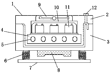
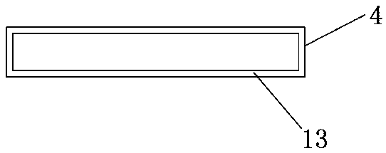
[0021] Such as Figure 1-2 Shown, a kind of injection mold for refrigerator drawer comprises mold main body 1, upper mold 2 and lower mold 3, and described mold main body 1 is made up of upper mold 2 and lower mold 3, and described upper mold 2 is positioned at lower mold 3 top, The inside of the mold main body 1 is provided with a heat dissipation pipe 4, the upper part of the heat dissipation pipe 4 is fixedly connected to the cavity 10, and the inside of the cavity 10 is provided with a semiconductor refrigerator 11, and the upper part of the cavity 10 is inlaid with a heat dissipation fan 9. An injection port 12 is installed at one end of the upper part of the mold body 1 , a graphene heat conduction layer 13 is inlaid on the inner wall of the heat dissipation pipe 4 , and ice crystals 5 are filled inside the heat dissipation pipe 4 .

[0022] In this embodiment, by setting ice crystal 5, graphene heat-conducting layer 13, semiconductor refrigerator 11 and heat dissipation...

Embodiment 2

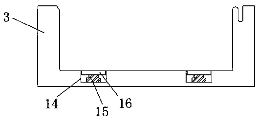
[0024] Such as figure 1 with image 3 As shown, vibrating springs 6 are installed at both ends of the bottom of the lower mold 3, the bottom of the vibrating spring 6 is fixedly connected to the connecting base 7, the lower mold 3 is connected to the connecting base 7 through the vibrating spring 6, and the lower mold 3 The bottom is provided with a vibrating motor 8, and both ends of the lower mold 3 are inlaid with sliding grooves 14, the inner wall of the sliding groove 14 is slidingly connected to the sliding block 16, and the sliding block 16 and the upper surface of the lower mold 3 are located on the same horizontal plane. A hydraulic rod 15 is mounted on the inner bottom side of the sliding groove 14 , and the upper part of the hydraulic rod 15 is engaged with the sliding block 16 .

[0025] In this embodiment, by setting the vibrating motor 8 and the vibrating spring 6, the uniformity of the molding of the mold body 1 is effectively improved, and bubble grooves are a...


PUM


Abstract

The invention discloses an injection mold for a refrigerator drawer. The injection mold comprises a mold main body, an upper mold body and a lower mold body, wherein the mold main body is composed ofthe upper mold body and the lower mold body, the upper mold body is positioned above the lower mold body, a heat dissipation pipeline is arranged inside the mold main body, a cavity is fixedly connected to the upper part of the heat dissipation pipeline, a semiconductor refrigerator is arranged inside the cavity, a heat dissipation fan is inlaid at the upper part of the cavity, and an injection molding opening is formed in one end of the upper part of the mold main body. According to the mold, by arranging an ice crystal, a graphene heat conduction layer, a semiconductor refrigerator and the heat dissipation fan, the upper mold body is effectively cooled, the cooling effect of the mold main body is improved, cooling forming of the refrigerator drawer is facilitated, the forming uniformityof the mold main body is effectively improved by arranging a vibration motor and a vibration spring, bubble grooves and the like are avoided, the formed refrigerator drawer can be slowly pushed out ofthe mold by arranging a hydraulic rod and a sliding block, and the lower mold body can be conveniently separated from the refrigerator drawer.

Description

technical field [0001] The invention relates to an injection mold, in particular to an injection mold for a refrigerator drawer. Background technique [0002] A refrigerator is a kind of refrigeration equipment that maintains a constant low temperature, and it is also a civilian product that keeps food or other items in a constant low temperature and cold state. There are compressors and ice machines in the box to freeze the cabinet or box, with a refrigeration device Storage boxes and refrigerator drawers are refrigerator parts. [0003] However, the general injection mold for refrigerator drawers does not have the function of cooling, and the composition is not uniform enough during the molding process, which is prone to air bubbles. Therefore, we propose an injection mold for refrigerator drawers. Contents of the invention [0004] The main purpose of the present invention is to provide an injection mold for refrigerator drawers. By setting ice crystals, graphene heat-...

Claims


Application Information

Patent Timeline
Patent Type & Authority Applications(China)
IPC IPC(8): B29C45/26B29C45/17B29C45/73B29C45/40
CPCB29C45/1701B29C45/2602B29C45/401B29C45/7331B29L2031/7622
Inventor 胡翔
Owner 合肥高科科技股份有限公司
Why Eureka
Try Eureka