Eureka AIR delivers breakthrough ideas for toughest innovation challenges, trusted by R&D personnel around the world.

Method for stopping water at joints between occlusive piles and diaphragm retaining wall

A technology of occlusal piles and ground-connected walls, which is applied in the field of construction engineering, can solve problems such as the difficulty of plugging leaks, affecting the safety of foundation pits and surrounding environments, and achieve the goals of enhancing stability and safety, and improving waterproof and anti-leakage performance Effect

Inactive Publication Date: 2019-11-05
THE FOURTH ENG CO LTD OF CHINA RAILWAYNO 20 BUREAU GRP +1
View PDF9 Cites 3 Cited by
  • Summary
  • Abstract
  • Description
  • Claims
  • Application Information

AI Technical Summary

Problems solved by technology

However, the problem of water-stopping at the joints between the occlusal piles and the underground diaphragm wall is a major and difficult point. Once water leakage occurs at the joints between the occlusal piles and the underground diaphragm wall, not only is it very difficult to stop the leakage, but it will also affect the foundation pit and the surrounding environment safety
At present, there is no effective system construction method

Method used


Image

  • Method for stopping water at joints between occlusive piles and diaphragm retaining wall
  • Method for stopping water at joints between occlusive piles and diaphragm retaining wall

Examples


Embodiment 1

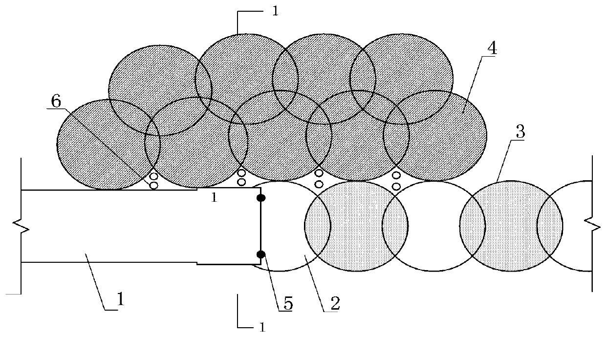
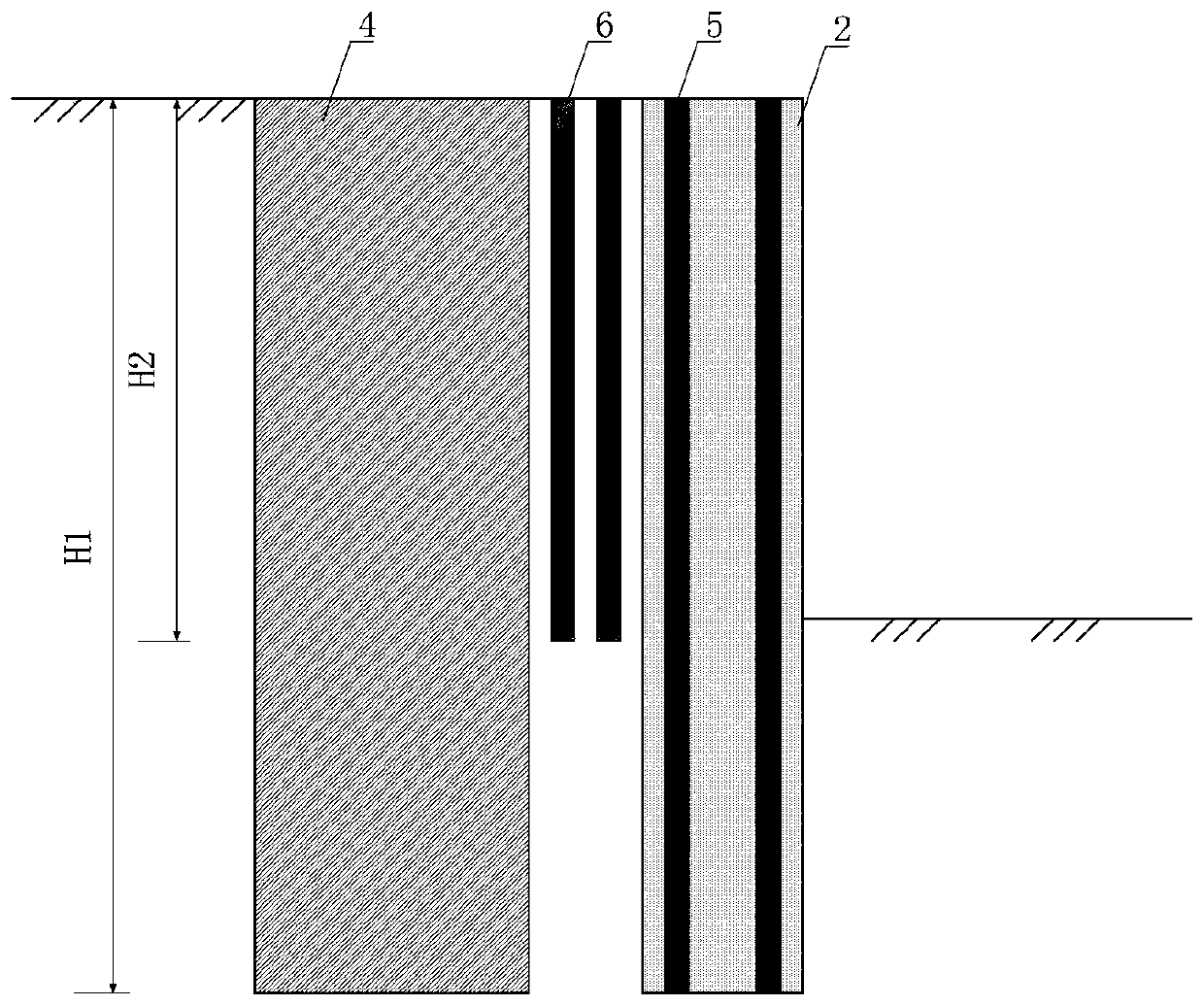
[0032]The main structure of the water-stop structure at the joint between the occlusal pile and the ground connection wall in this embodiment includes the ground connection wall 1, the occlusion pile 2, the occlusion pile 3, the rotary spray pile 4, the steel flower pipe 5 and the grouting pipe 6. The occlusal piles and the occlusal piles 3 and the occlusal piles 2 are arranged at intervals, interlocking to form an occlusal pile, the ground connection wall 1 is occluded with the adjacent occlusal pile 2, and the buried depth of the underground diaphragm wall 1 is the same as that of the adjacent occlusal pile 2. The burial depth is the same; the steel flower tube 5 is welded on the reinforcement cage on the adjacent side of the ground connection wall 1 and the adjacent occlusal pile 2, and the burial depth is the same as that of the ground connection wall 1; the grouting pipe 6 is buried in the occlusion pile 2 and the ground connection wall 1 outside the joint, the buried dept...

Embodiment 2

[0035] In this embodiment, the water-stopping structure at the joint between the occlusal pile and the ground wall described in Example 1 is applied to the joint between the occlusal pile and the underground diaphragm wall in a certain subway station, and the water-stop at the joint between the occlusal pile and the ground wall The main structure of the structure includes the ground connection wall 1, the wall thickness is 800mm, the width is 6.0m, and the buried depth is 26m. It is poured with C45 underwater concrete; The burial depth is 26m, poured with C25 ultra-retarded concrete; 3 occlusal piles, 1000mm in diameter, 700mm away from adjacent piles, 300mm in occlusal, 26m deep, poured with C45 underwater concrete; 4 rotary grouting piles, 1000mm in diameter , with a buried depth of 26m, 4 rotary grouting piles interlocked by 300mm, tangent to the ground connection wall 1, occlusal pile 2, and occlusal pile 3, poured with ordinary Portland cement with a label of 42.5; steel f...


PUM


Abstract

The invention belongs to the technical field of construction engineering, and relates to a method for stopping water at the joints between occlusive piles and a diaphragm retaining wall. Occlusive pile concrete piles and occlusive pile plain concrete piles are arranged at intervals and are connected with each other in an occlusive manner to form the occlusive piles. The diaphragm retaining wall isconnected with the adjacent occlusive pile plain concrete piles in an occlusive manner, and steel flower tubes are welded to the diaphragm retaining wall and the portions, on the adjacent sides of the adjacent occlusive pile plain concrete piles, of a reinforcing bar cage. Grouting pipes are buried into the outer sides of the joints of the occlusive pile plain concrete piles and the diaphragm retaining wall. Jet grouting piles are arranged on the outer sides of the joints of the occlusive pile plain piles and the diaphragm retaining wall. Through the occlusion of the diaphragm retaining walland adjacent pile bodies, the steel flower tubes are buried between a diaphragm retaining wall body and the occlusive piles, the double rows of grouting pipes are arranged on the outer sides of the joints of the diaphragm retaining wall and the occlusive piles, and jet grouting pile reinforcing is carried out on the outer sides of the occlusive piles and the diaphragm retaining wall; and by usingthe series of structure and measures, the problem of water stop at the joints of the occlusive piles and the diaphragm retaining wall is solved, the waterproof performance and leakage-proof performance of the joints are improved, and the stability and safety of a foundation pit are improved.

Description

Technical field: [0001] The invention belongs to the technical field of construction engineering, and relates to a water-stopping method at the joint between an occlusal pile and an underground continuous wall of a foundation pit support structure. Background technique: [0002] With more and more subway projects in our country, all kinds of buildings around the foundation pits of urban subways are dense, the surrounding environment and water and land geological conditions are complex, and the construction is difficult. It is necessary to explore new foundation pit support methods. [0003] At present, the foundation pit support forms commonly used in subway engineering include occlusal piles and underground diaphragm walls. The occlusal pile refers to the foundation pit support structure formed by the interlocking of reinforced concrete piles and plain piles between the adjacent piles in the row of piles arranged in the plane, which is used as the foundation pit support str...

Claims


Application Information

Patent Timeline
Patent Type & Authority Applications(China)
IPC IPC(8): E02D29/16E02D31/02E02D17/04
CPCE02D17/04E02D29/16E02D31/02
Inventor 郭海涛韩超宁凯飞
Owner THE FOURTH ENG CO LTD OF CHINA RAILWAYNO 20 BUREAU GRP
Why Eureka
Eureka Blog
Learn More