Street-applied lighting engineering equipment with good heat dissipation effect

A heat dissipation effect and engineering equipment technology, applied in lighting and heating equipment, mechanical equipment, cooling/heating devices of lighting devices, etc., can solve problems such as reducing power generation efficiency, component burnout, and reducing service life, so as to improve heat dissipation effect , strong realizability and ingenious structure

Inactive Publication Date: 2019-11-05
SHENZHEN NAISHIDI TECH DEV CO LTD
View PDF0 Cites 3 Cited by
  • Summary
  • Abstract
  • Description
  • Claims
  • Application Information

AI Technical Summary

Problems solved by technology

[0003] Existing solar street lamps will generate a lot of heat during use, and high temperature will accelerate the aging speed of the internal components of the LED lamp, and even cause the components to burn out in serious cases. In the prior art, it is generally installed inside or outside The heat dissipation mechanism, and because the current technicians are mainly conducting research on energy saving, the heat dissipation mechanism is generally designed to be relatively simple, so that the expected heat dissipation effect cannot be achieved, and the service life is reduced. Not only that, after long-term use, solar energy There will be more dust on the power generation board, and the dust will affect the absorption of light by the solar power generation board to realize photovoltaic power generation, reducing the power generation efficiency

Method used


Image

  • Street-applied lighting engineering equipment with good heat dissipation effect
  • Street-applied lighting engineering equipment with good heat dissipation effect
  • Street-applied lighting engineering equipment with good heat dissipation effect

Examples


Embodiment Construction

[0026] The present invention is described in further detail now in conjunction with accompanying drawing. These drawings are all simplified schematic diagrams, which only illustrate the basic structure of the present invention in a schematic manner, so they only show the configurations related to the present invention.

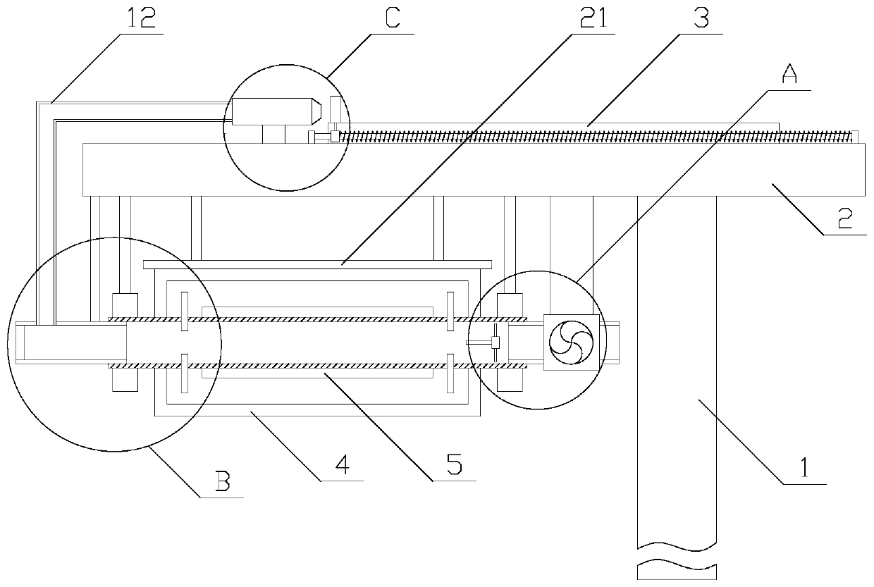
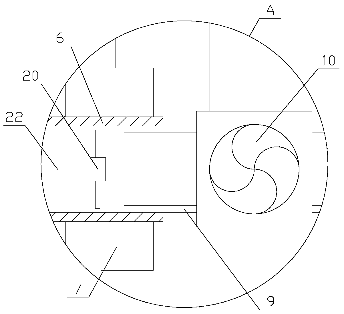
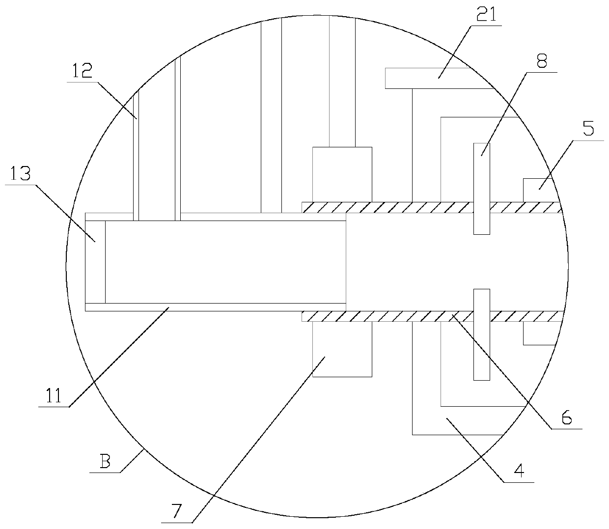
[0027] Such as Figure 1-2 As shown, a kind of lighting engineering equipment with good heat dissipation effect for the street includes a lamp post 1, a lamp arm 2, a solar panel 3, a lampshade 4 and at least two lamp tubes 5, and the lamp arm 2 and the lamp post 1 Vertically, the lamp arm 2 is fixed on the top of the lamp post 1, the solar panel 3 is arranged on the top of the lamp arm 2, the lampshade 4 is arranged on the side of the lamp arm 2 away from the solar panel 3, and the lamp tube 5 is arranged in the lampshade 4, the lampshade 4 is provided with a heat dissipation mechanism, and the side of the lamp arm 2 provided with the solar panel 3 is provid...


PUM


Abstract

The invention relates to street-applied lighting engineering equipment with a good heat dissipation effect. The equipment comprises a lamp pole, a lamp arm, a solar panel, a lampshade and at least twotubes, wherein the lamp arm is perpendicular to the lamp pole, the lamp arm is fixed to the top end of the lamp pole, the solar panel is arranged at the top of the lamp arm, the lampshade is arrangedat the side, away from the solar panel, of the lamp arm, the tubes are arranged in the lampshade, a heat dissipation mechanism is arranged in the lampshade, a cleaning mechanism is arranged at the side, provided with the solar panel, of the lamp arm, and the heat dissipation mechanism comprises a rotating pipe, an actuation component, two bearings and two heat dissipation components. According tothe street-applied lighting engineering equipment with the good heat dissipation effect, the heat dissipation effect is improved through the heat dissipation mechanism; and moreover, the function ofremoving dust on the solar panel is achieved through the cleaning mechanism, and therefore the situation that the dust influences the power generation efficiency of the solar panel is avoided.

Description

technical field [0001] The invention relates to the field of lighting engineering, in particular to lighting engineering equipment with good heat dissipation effect for streets. Background technique [0002] The lighting project is also called the city glory project, which refers to the lighting of shopping malls, tourist attractions, and places with a lot of traffic in the streets in order to beautify the urban environment and improve the overall image of the city. Among them, solar street lamps are part of the lighting project Common equipment, solar street lights are generally set on both sides of the street or road to provide lighting for the road. [0003] Existing solar street lamps will generate a lot of heat during use, and high temperature will accelerate the aging speed of the internal components of the LED lamp, and even cause the components to burn out in serious cases. In the prior art, it is generally installed inside or outside The heat dissipation mechanism,...

Claims


Application Information

Patent Timeline
IPC IPC(8): F21S9/03F21V23/00F21V29/71F21V29/85H02S40/10F21W131/103
CPCF21S9/037F21V23/003F21V29/717F21V29/85F21W2131/103H02S40/10Y02B20/72Y02E10/50
Inventor 武桂英
Owner SHENZHEN NAISHIDI TECH DEV CO LTD
Why Eureka
Try Eureka