A Design Method of FPGA-based Steady-state Visual Evoked Potential Brain-Computer Interface System

A steady-state visual evoked and system design technology, applied in computing, mechanical mode conversion, computer components, etc., can solve problems such as frame drop, steady-state visually evoked potential light flicker stimulation, etc., to reduce requirements, save development costs, The effect of improving operating efficiency

Active Publication Date: 2021-01-15
XI AN JIAOTONG UNIV
View PDF6 Cites 0 Cited by
  • Summary
  • Abstract
  • Description
  • Claims
  • Application Information

AI Technical Summary

Problems solved by technology

However, the induction of steady-state visual evoked potentials requires light flickering at a stable frequency for stimulation. Ordinary computers are prone to "frame drop" and other phenomena during this process, so hardware devices with better performance are needed to complete the stimulation generation process.

Method used


Image

  • A Design Method of FPGA-based Steady-state Visual Evoked Potential Brain-Computer Interface System
  • A Design Method of FPGA-based Steady-state Visual Evoked Potential Brain-Computer Interface System
  • A Design Method of FPGA-based Steady-state Visual Evoked Potential Brain-Computer Interface System

Examples


Embodiment Construction

[0036] The present invention will be further described in detail below in conjunction with the accompanying drawings and embodiments.

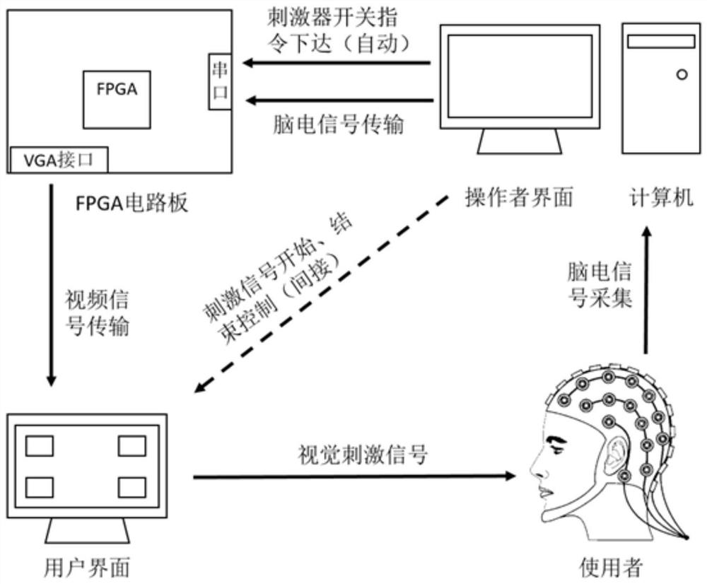
[0037] refer to figure 1 , a method for designing a steady-state visual evoked potential brain-computer interface system based on FPGA, comprising the following steps:

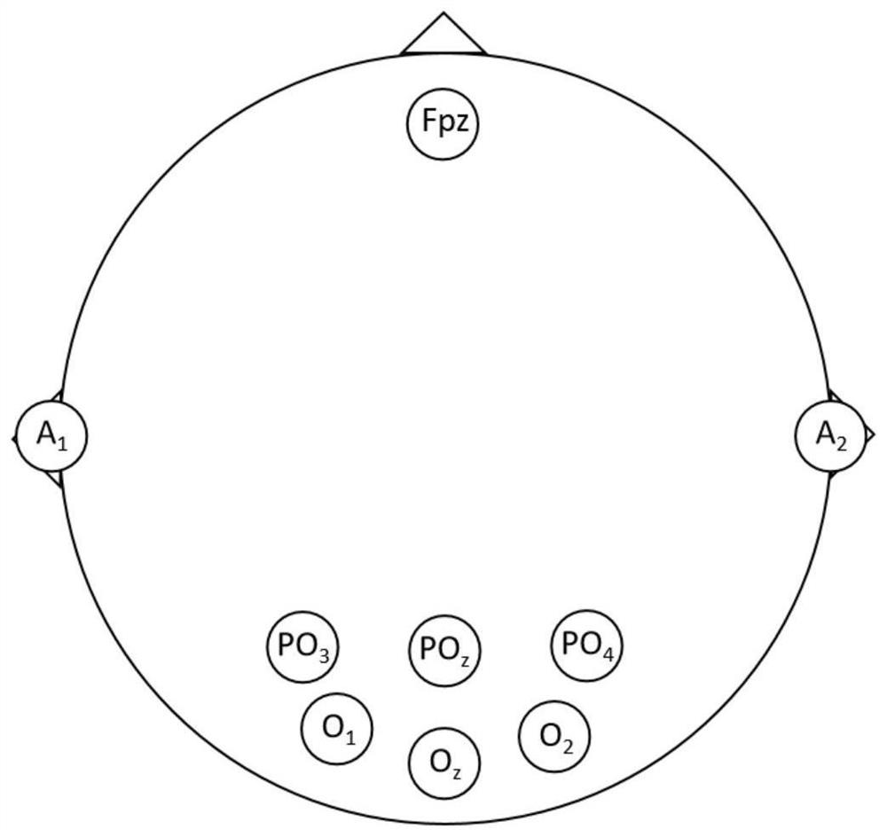
[0038] Step 1, such as figure 2 As shown, according to the international standard lead 10-20 system, the EEG signal measurement electrodes are placed on the PO of the visual occipital area of ​​the user's head through the EEG cap. 3 、PO z 、PO 4 , O 1 , O z and O 2 Position, place the ground electrode at the Fpz position of the forehead, and place the ground electrode at any earlobe position A1 or A 2 The reference electrode is placed, and the measured EEG signal is amplified by professional acquisition equipment, converted from analog to digital, and then transmitted to the computer;

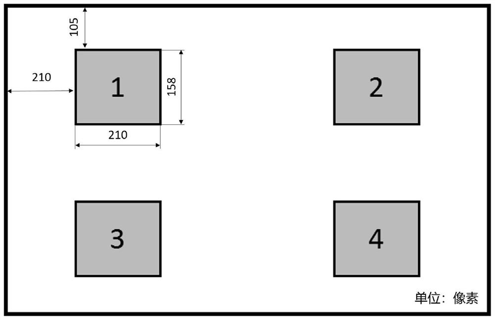
[0039] Step 2, refer to image 3 , present four steady-state stimulation units fli...


PUM


Abstract

The invention discloses a steady-state visual evoked potential brain-computer interface system design method based on an FPGA, and the method comprises the steps: placing an electroencephalogram signal collection electrode in a pillow region of the head of a user, and transmitting a measured electroencephalogram signal to an FPGA circuit board in real time for processing; displaying avisual stimulation unit on a user interface through the FPGA circuit board; in the stimulation process, overturning a stimulation rectangle according to red and black colors to form a flicker stimulation unit with a fixed frequency; then enabling the user to watche any stimulation unit of the user interface; enabling the computer to synchronously collect and store electroencephalogram signals of the user andsends the electroencephalogram signals to the FPGA circuit board in real time, after the FPGA receives an end instruction, carrying out fast Fourier transformation on the obtained electroencephalogramsignals, frequency components related to a stimulation normal form are analyzed, and the stimulation target position where an electroencephalogram signal frequency domain induction peak value is located is calculated. According to the method, the execution efficiency of the brain-computer interface system is improved, and the implementation cost of the steady-state visual evoked potential brain-computer interface is reduced.

Description

technical field [0001] The invention relates to the field of digital IC design of neural engineering, brain-computer interface technology and electronic information engineering in biomedical engineering, and specifically relates to a design method of a steady-state visual evoked potential brain-computer interface system based on FPGA. Background technique [0002] Brain-computer interface is a technology that establishes abnormal neural pathways between the human brain and external devices. It measures and analyzes EEG signals and finally converts them into control instructions for devices. Due to the large amount of EEG data and complex processing algorithms, conventional brain-computer interfaces generally use computers to process EEG signals and generate control instructions. widespread promotion. [0003] Steady-state visual evoked potential (SSVEP) appears at a specific time and in a specific area of ​​the cerebral cortex, compared with P300 event-related potential, ev...

Claims


Application Information

Patent Timeline
Patent Type & Authority Patents(China)
IPC IPC(8): G06F3/01
CPCG06F3/015
Inventor 谢俊张彦军曹国智薛涛徐光华李敏
Owner XI AN JIAOTONG UNIV
Why Eureka
Try Eureka