
Thermal power plant pipeline stress coupling analysis system and analysis method

A thermal power plant, coupled analysis technology, applied in pipeline systems, electrical digital data processing, special data processing applications, etc., to achieve the effect of state monitoring, conducive to problem discovery, and risk assessment

Pending Publication Date: 2019-11-05
HUADIAN ELECTRIC POWER SCI INST CO LTD
View PDF4 Cites 4 Cited by
  • Summary
  • Abstract
  • Description
  • Claims
  • Application Information

AI Technical Summary

Problems solved by technology

[0009] The purpose of the present invention is to overcome the above-mentioned deficiencies in the prior art, and to provide a reasonable structural design, which can not only solve the problem of how to quickly calculate the stress of the piping system, but also perform stress analysis on-line according to the change of the operating parameters of the piping system. Pipeline stress coupling analysis system and analysis method for thermal power plant for risk warning

Method used


Image

  • Thermal power plant pipeline stress coupling analysis system and analysis method
  • Thermal power plant pipeline stress coupling analysis system and analysis method
  • Thermal power plant pipeline stress coupling analysis system and analysis method

Examples


Embodiment Construction

[0062] The present invention will be further described in detail below in conjunction with the accompanying drawings and examples. The following examples are explanations of the present invention and the present invention is not limited to the following examples.

[0063] Example.

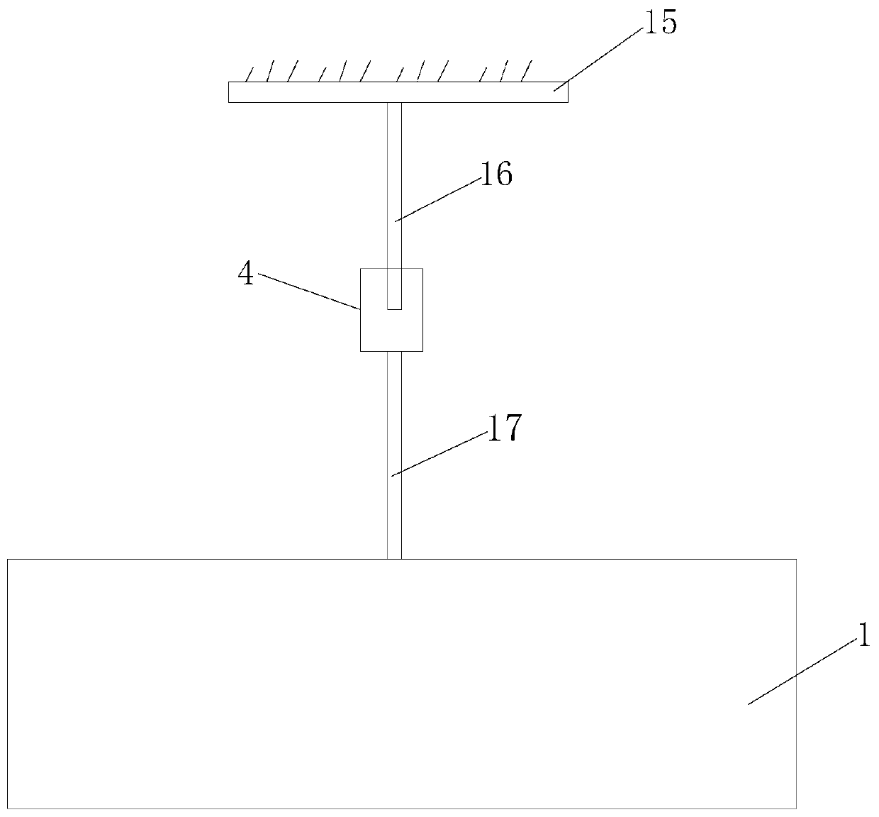
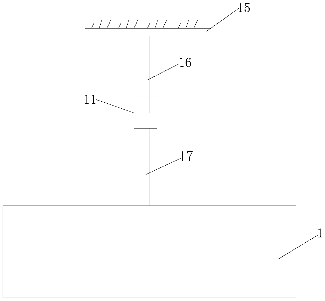
[0064] see Figure 1 to Figure 7 It should be noted that the structures, proportions, sizes, etc. shown in the drawings attached to this specification are only used to match the content disclosed in the specification, for those who are familiar with this technology to understand and read, and are not used to limit the present invention Therefore, it has no technical substantive meaning, and any modification of structure, change of proportional relationship or adjustment of size shall still fall into the within the scope covered by the technical content disclosed in the present invention. At the same time, if there are terms such as "upper", "lower", "left", "right", "middle" and "one" in this spe...


PUM


Abstract

The invention relates to a thermal power plant pipeline stress coupling analysis system and analysis method. A front-end suspender force sensor is mounted on a front-end fixed hanging bracket; the rear-end suspender force sensor is mounted on the rear-end fixed hanging bracket; the spring hanger left side force sensor and the spring hanger right side force sensor are installed on the two sides ofthe spring hanger respectively. The front-end pipeline wall temperature sensor, the front-end pipeline pressure sensor, the flow sensor, the rear-end pipeline wall temperature sensor and the rear-endpipeline pressure sensor are all installed on a pipeline. The front-end pipeline wall temperature sensor, the front-end suspender force sensor, the front-end pipeline pressure sensor, the flow sensor,the rear-end pipeline wall temperature sensor, the rear-end pipeline pressure sensor, the rear-end suspender force sensor and the spring hanger right side force sensor are all connected with the computer. The thermal power plant pipeline stress coupling analysis system and the analysis method are high in technical content, high in innovativeness, high in safety value, practical and good in operability.

Description

technical field [0001] The invention relates to a thermal power plant pipeline stress coupling analysis system and analysis method. Background technique [0002] At present, there are many software for pipeline stress calculation on the market, and the technology is relatively mature. These stress analysis softwares all establish models in advance, and then perform stress calculations under various loads to obtain stresses under various working conditions. ANSYS software is a large-scale general-purpose finite element analysis (FEA) software developed by ANSYS Corporation of the United States, which can perform structural static analysis, structural dynamic analysis, structural nonlinear analysis, dynamic analysis, and thermal analysis. CAESARII pipeline stress analysis software is a professional software for pressure pipeline stress analysis developed by COADE Company of the United States. It can analyze and calculate static analysis and dynamic analysis. Bentley AutoPIPE...

Claims


Application Information

Patent Timeline
IPC IPC(8): G06F17/50F17D5/00
CPCF17D5/00
Inventor 冯亦武
Owner HUADIAN ELECTRIC POWER SCI INST CO LTD
Learn More