Online vacuum oiling device for oil conservator and using method of online vacuum oiling device

An oil injection device and oil conservator technology, which is applied in the direction of electrical component structure associations, electrical components, transformer/inductor parts, etc., can solve the problems of fast oil flow in the device, equipment monitoring operation, low oil level in the oil conservator, etc., to achieve Ensure the stability of oil injection, solve the light gas action, and ensure the effect of judgment accuracy

Pending Publication Date: 2019-11-05
MAINTENANCE BRANCH COMPANY STATE GRID ZHEJIANG ELECTRIC POWER +3
View PDF0 Cites 9 Cited by
  • Summary
  • Abstract
  • Description
  • Claims
  • Application Information

AI Technical Summary

Problems solved by technology

[0002] At present, oil-immersed transformers or reactors leak and leak oil during operation. When the equipment leaks lightly during heavy load, it is difficult to apply for a system power outage, and defective equipment needs to be monitored for operation.
There is continuous oil leakage in a certain part of the body of the oil-immersed transformer or reactor, which causes the oil level in the oil conservator to be too low. In case of low temperature or sudden temperature change in winter, the oil level of the body drops rapidly, causing the light gas relay to operate, and there is an accident. risk of blackout
[0003] The existing devices all adopt the method of vacuum filling and filtering oil after the equipment is powered off. The device has a fast oil flow rate, a large volume, and inconvenient operation.
If the existing equipment is used for online vacuum injection and filtering of oil, there are the following problems: 1. The risk of heavy gas action caused by too fast oil flow; 2. The risk of vacuum damage to the transformer or reactor as a whole

Method used


Image

  • Online vacuum oiling device for oil conservator and using method of online vacuum oiling device

Examples


Embodiment Construction

[0027] The technical solution of the present invention will be further described in detail below in conjunction with the accompanying drawings.

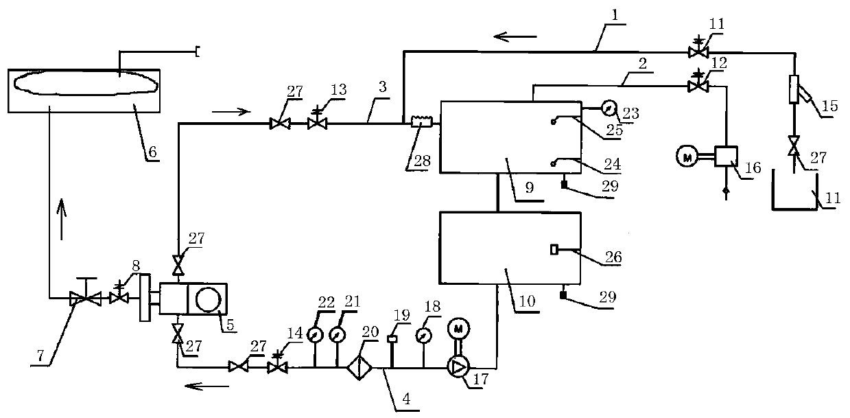
[0028] Such as figure 1 As shown, the oil pillow online vacuum oiling device includes a vacuum cylinder 9, a pure oil cylinder 10, an oil storage pipeline 1, a vacuum pipeline 2, an oil injection pipeline 4, an oil return pipeline 3 and a three-way valve 5; the vacuum pipeline 2 and the vacuum The vacuum interface of the cylinder 9 is connected, and the vacuum pipeline 2 is provided with a vacuum solenoid valve 12 and a vacuum pump 16; the oil outlet of the vacuum cylinder 9 is connected with the oil inlet of the pure oil cylinder 10; the oil outlet of the oil injection pipeline 4 is connected with the The three-way valve 5 is detachably connected, the oil inlet of the oil injection pipeline 4 is connected with the oil outlet of the pure oil cylinder 10; one end of the oil return pipeline 3 is connected with the oil storage inlet of ...


PUM


Abstract

The invention discloses an online vacuum oiling device for an oil conservator, and relates to the field of vacuum oiling devices for oil-immersed transformers or reactors. When an oil-immersed transformer or a reactor slightly leaks oil in a large-load period, the power failure is difficult to apply, but an existing device adopts a vacuum oil injection and filtration mode after power failure of the equipment, so the oil flow of the device is high, and if online vacuum oil injection and filtration is carried out, the overall vacuum of the transformer or reactor is easily damaged, and heavy gasaction can be caused when the oil flow speed is too high. The device comprises a vacuum cylinder, a pure oil cylinder, an oil storage pipeline, a vacuumizing pipe, an oil injection pipe, an oil returnpipe and a three-way valve. When the device is in use, all the pipes are connected firstly, air is exhausted from the pipes, and then oil is injected into the oil conservator, and oil is collected from the pipes after oil injection is finished. The problem of online vacuum oil injection and filtration without power failure is solved, air is prevented from being injected into the oil conservator,the risk caused by overall vacuum damage to an oil loop is avoided, and the light gas action risk caused by over-low oil level due to continuous light oil leakage is effectively solved.

Description

technical field [0001] The invention relates to the field of vacuum oiling devices for oil-immersed transformers or reactors, in particular to an online vacuum oiling device for an oil conservator and a use method thereof. Background technique [0002] At present, oil-immersed transformers or reactors leak and leak oil during operation. When the equipment leaks oil slightly during heavy load, it is difficult to apply for a system power outage, and defective equipment needs to be monitored for operation. There is continuous oil leakage in a certain part of the body of the oil-immersed transformer or reactor, which causes the oil level in the oil conservator to be too low. In case of low temperature or sudden temperature change in winter, the oil level of the body drops rapidly, causing the light gas relay to operate, and there is an accident. Risk of power outage. [0003] The existing devices all adopt the method of vacuum filling and filtering oil after the equipment is po...

Claims


Application Information

Patent Timeline
Patent Type & Authority Applications(China)
IPC IPC(8): H01F27/14H01F27/40
CPCH01F27/14H01F27/402H01F2027/406
Inventor 曹力潭魏华兵沈正元石明垒焦晨骅张健步顺德苗瑜朱玉婷蔡东伟陈文强王生祺年长春代顺锋沈军艇
Owner MAINTENANCE BRANCH COMPANY STATE GRID ZHEJIANG ELECTRIC POWER
Why Eureka
Try Eureka