Mechanical interlocking mechanism between upper and lower drawers of low-voltage drawer cabinet

A technology of interlock mechanism and drawer cabinet, which is applied in the direction of pull-out switch cabinets, switchgear, electrical components, etc., can solve the problems of only electrical interlocking, etc., and achieve the advantages of improving maintenance convenience, simple structure, and realizing safety and reliability Effect

Pending Publication Date: 2019-11-05
SHANDONG TAIKAI VACUUM SWITCH
View PDF0 Cites 0 Cited by
  • Summary
  • Abstract
  • Description
  • Claims
  • Application Information

AI Technical Summary

Problems solved by technology

At present, the two plastic case switches (manually operated inside the drawer) have only electrical interlocking. In order to improve safety and reliability, this mechanical interlocking mechanism is designed and developed.

Method used


Image

  • Mechanical interlocking mechanism between upper and lower drawers of low-voltage drawer cabinet
  • Mechanical interlocking mechanism between upper and lower drawers of low-voltage drawer cabinet
  • Mechanical interlocking mechanism between upper and lower drawers of low-voltage drawer cabinet

Examples


Embodiment Construction

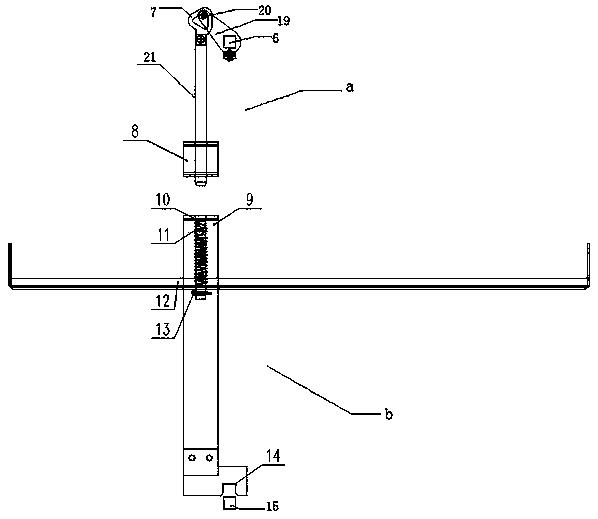
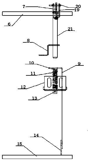
[0025] As shown in the figure, the present invention is a mechanical interlock mechanism between the upper and lower drawers of a low-voltage drawer cabinet. There is a partition 28 inside, and the partition 28 divides the main cabinet body 1 into 1# incoming line drawer, 2# incoming line drawer, outgoing line circuit, main busbar room and cable room, and the top of the main cabinet body is horizontally equipped with a main busbar room 16 , the lower side is the cable room 17, and the other side is 1# incoming line drawer 2, 2# incoming line drawer 3 and outgoing line circuit 4 from bottom to top, and the busbar 27 vertically runs through 1# incoming line drawer, 2# Incoming line drawer and outgoing line circuit 4, busbars are divided into three groups, namely A-phase busbar, B-phase busbar and C-phase busbar. connect.

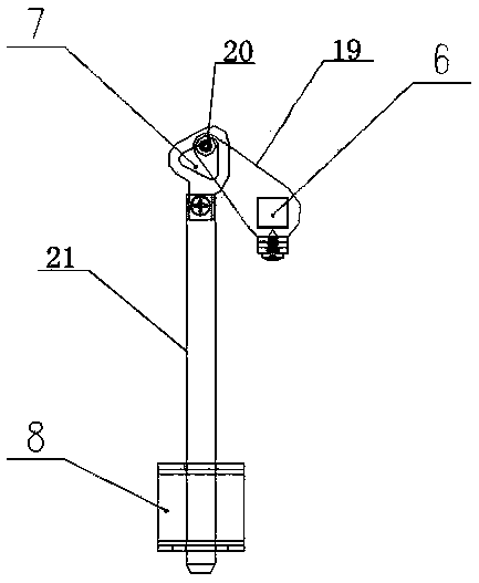
[0026] The mechanical interlocking mechanism is set in the 1# incoming line drawer 2 and the 2# incoming line drawer 3. The mechanical interlocking mechanism...


PUM


Abstract

The invention discloses a mechanical interlocking mechanism between the upper drawer and the lower drawer of the low-voltage drawer cabinet. A second operation square shaft serves as the axis, the second operation square shaft rotates forwards or backwards, and the other end of a connecting part rotates in a triangular core, thereby achieving the vertical up-and-down movement of a square rod; a second incoming line drawer carries out closing operation, the second operation square shaft rotates clockwise by 90 degrees, the square rod is pressed downwards, and vertically moves downwards after passing through a bottom plate, a layer partition plate and a supporting plate of the second incoming line drawer, so that a clamping part at the bottom is downwards clamped on the first operation square shaft, and at the moment, a first operation square shaft in the first incoming line drawer cannot be switched on for rotating operation, thereby achieving the interlocking purpose; when the second incoming line drawer is switched off, the second operating square shaft rotates 90 degrees anticlockwise, the square rod is vertically upward, the supporting plate is reset under the action of a springand a pin, the clamping part is separated from the first operating square shaft, and the first operating square shaft can be switched on normally. The structure is simple, a molded shell switch is arranged in the drawer, the maintenance convenience is improved, and the safety and reliability are realized through mechanical interlocking.

Description

technical field [0001] The invention relates to the technical field of low-voltage switch cabinets, in particular to a mechanical interlocking mechanism between upper and lower drawers of a low-voltage drawer cabinet. Background technique [0002] With the rapid development of power grid construction, the demand for various switch cabinets continues to increase, especially the MNS drawer cabinet has the advantages of simple interlocking mechanism, safety and reliability, flexible interchange of drawers, high safety performance, and good protection level. The market prospect broad. [0003] In order to ensure the continuous reliability of power supply, the MNS incoming line is often set up with two incoming lines plus one connection incoming line scheme. The incoming line switch of this scheme is generally a frame circuit breaker switch. In addition to the electrical interlock of automatic switching, the mechanical interlock is realized by means of three locks and two keys. ...

Claims


Application Information

Patent Timeline
IPC IPC(8): H02B11/133H01H9/26
CPCH02B11/133H01H9/26
Inventor 申春青王凯杨青
Owner SHANDONG TAIKAI VACUUM SWITCH
Why Eureka
Try Eureka