Spraying device used for automobile part machining

A technology for auto parts and spraying devices, applied in the direction of spraying devices, etc., can solve problems such as manual spraying, and achieve the effects of improving quality, facilitating cleaning, and reducing spraying time

Active Publication Date: 2019-11-08
惠州信邦精密部件有限公司
View PDF7 Cites 6 Cited by
  • Summary
  • Abstract
  • Description
  • Claims
  • Application Information

AI Technical Summary

Problems solved by technology

[0004] The purpose of the present invention is to provide a spraying device for auto parts processing, which has the advantages of automatic spraying, and solves the problem that the common spraying devices for auto parts processing are mostly manual spraying

Method used


Image

  • Spraying device used for automobile part machining
  • Spraying device used for automobile part machining
  • Spraying device used for automobile part machining

Examples


Embodiment 1

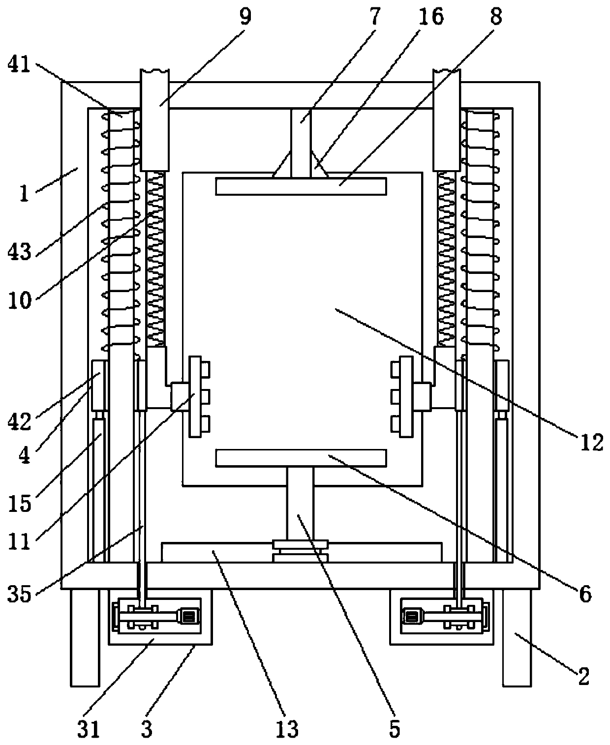
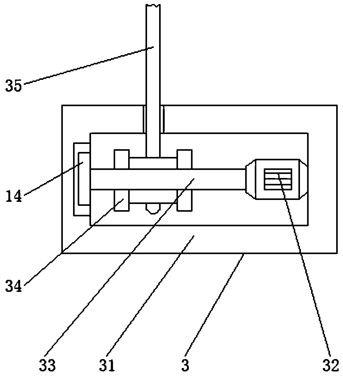
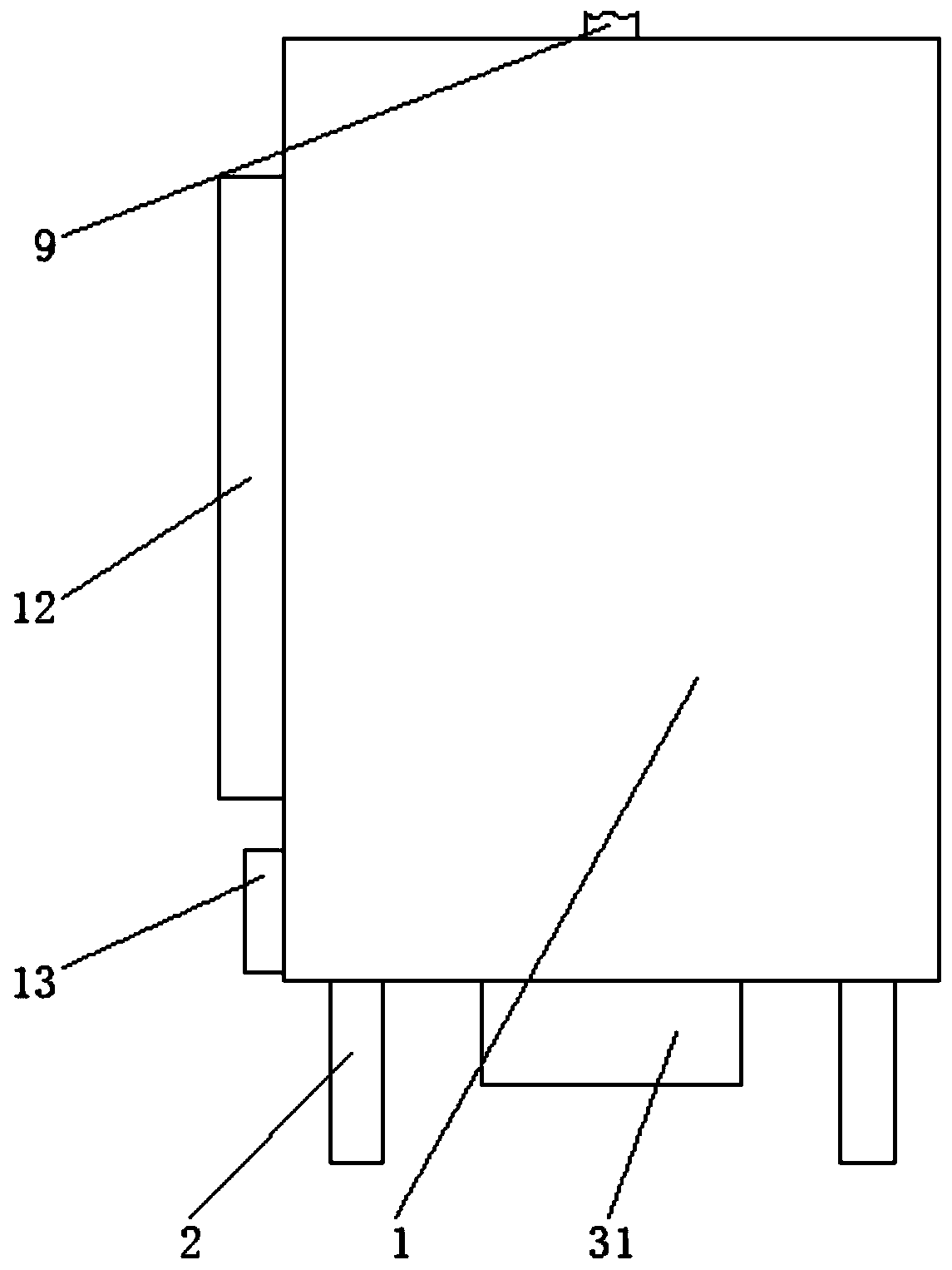
[0022] Example 1: See figure 1 or image 3 , a kind of spraying device for auto parts processing, comprising a fixed shell 1, the four corners of the bottom of the fixed shell 1 are fixedly connected with a support plate 2, by setting the support plate 2, it plays a role of supporting the fixed shell 1, and the bottom of the fixed shell 1 The left and right sides of the fixed shell 1 are fixedly connected with adjusting devices 3, the left and right sides of the inner wall of the fixed shell 1 are equipped with movable devices 4, the midpoint of the bottom of the fixed shell 1 inner wall is fixedly connected with a cylinder 5, and the top of the cylinder 5 is fixedly connected with a fixed Plate 6, the top of the inner wall of the fixed shell 1 and the position corresponding to the fixed plate 6 are fixedly connected with a connecting plate 7, the bottom of the connecting plate 7 is fixedly connected with a stable plate 8 that is compatible with the fixed plate 6, and the left...

Embodiment 2

[0027] Embodiment 2: On the basis of the first embodiment, a T-shaped thin bar with a scale is added inside each nozzle 11, so that the verticality of the workpiece when it is clamped and the centering or spacing of the workpiece on the fixed plate 6 Placement, the specific design is that each nozzle 11 is provided with a T-shaped thin strip inside, and the T-shaped thin strip includes a straight section and two transverse sections perpendicular to the straight section, and one end of the straight section is connected to the intersection point of the two transverse sections. Scale and all can be stretched and stretched on section and two transverse sections, and the end of these two transverse sections and the front end on the intersection point of two transverse sections are provided with magnetite, and the specific working process of this embodiment is as follows: use When first pulling out the T-shaped thin strips on the inner sides of the two nozzles 11 to make the straight...


PUM


Abstract

The invention discloses a spraying device used for automobile part machining. The spraying device used for automobile part machining comprises a fixed shell. Supporting plates are fixedly connected tothe four corners of the bottom of the fixed shell. Adjustment devices are fixedly connected to the left side and the right side of the bottom of the fixed shell. Movable devices are arranged on the left side and the right side of the inner wall of the fixed shell. A cylinder is fixedly connected to the midpoint of the bottom of the inner wall of the fixed shell. A fixed plate is fixedly connectedto the top end of the cylinder. According to the spraying device used for automobile part machining, through the cooperation of a rotary motor, a rotary shaft, a winding wheel, a fixing rope, slidingrods, sliding blocks, buffer springs, the cylinder, a connecting plate and a stabilizing plate, the effect of automatic spraying is achieved, the problem that most common spraying devices for automobile part machining adopt manual spraying is solved, the spraying time is shortened, the quality of sprayed products is improved, and the influence of long-term spraying on the bodies of workers is avoided; and the working efficiency is improved, labor consumption is reduced, and great convenience is brought to users.

Description

technical field [0001] The invention relates to the technical field of auto parts processing, in particular to a spraying device for auto parts processing. Background technique [0002] As the foundation of the automobile industry, auto parts are a necessary factor to support the sustainable and healthy development of the automobile industry. In particular, the current independent development and innovation in the auto industry, which is in full swing, requires a strong component system to support it. Automobile self-owned brand and technological innovation need parts and components as the basis, and the independent innovation of parts and components will generate a strong impetus to the development of the whole vehicle industry. It is difficult to burst out the R & D and innovation capabilities of the company. Without the support of a strong parts system, the self-owned brand will be unsustainable. When processing auto parts, it is necessary to use a spraying device to spr...

Claims


Application Information

Patent Timeline
Patent Type & Authority Applications(China)
IPC IPC(8): B05B13/02B05B13/04
CPCB05B13/0285B05B13/041B05B13/0278
Inventor 张鑫忠
Owner 惠州信邦精密部件有限公司
Why Eureka
Try Eureka