
Spiral pipe inner wall weld joint grinding device

A technology of spiral tube and servo drive device, which is applied to the details of milling machine equipment, metal processing equipment, milling machine equipment, etc., can solve the problems of low efficiency, different quality control, and difficult grinding operations, so as to ensure stability, The effect of ensuring accuracy

Inactive Publication Date: 2019-11-08
DONGHUA UNIV
View PDF6 Cites 14 Cited by
  • Summary
  • Abstract
  • Description
  • Claims
  • Application Information

AI Technical Summary

Problems solved by technology

[0002] At present, for the grinding of the inner wall of the pipe with a diameter of more than 600mm and a length of more than 10000mm, most of them use manual work, which is difficult and inefficient, and the quality control varies from person to person
Existing in-pipeline grinding robots are mostly aimed at small pipelines, and are rarely used for friction stir welding weld grinding. This is because the friction stir welding welds have sharp flashes, burrs and depressions. The stability of the operation robot used for friction stir welding pipelines is insufficient, and it cannot meet the quality requirements of the pipeline grinding surface

Method used


Image

  • Spiral pipe inner wall weld joint grinding device
  • Spiral pipe inner wall weld joint grinding device

Examples


Embodiment Construction

[0021] The present invention will be further described below in conjunction with specific embodiments. It should be understood that these examples are only used to illustrate the present invention and not to limit the scope of the present invention. In addition, it should be understood that after reading the content taught by the present invention, those skilled in the art can make various changes or modifications to the present invention, and these equivalent forms also fall within the scope defined by the appended claims of the present application.

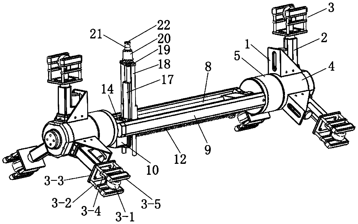
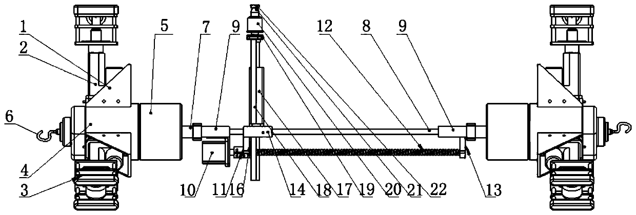
[0022] like figure 1 and figure 2 The shown device for grinding the inner wall of the spiral pipe includes a pipe support mechanism at both ends, a rotary feed mechanism and a grinding executive mechanism.

[0023] The pipeline support mechanism includes a central support base 4 and three self-lockable movable support feet 3 . The central support base 4 includes an integrally cast cylindrical hollow support shell and three m...


PUM


Abstract

The invention relates to a spiral pipe inner wall weld joint grinding device. The spiral pipe inner wall weld joint grinding device comprises pipeline supporting mechanisms at the two ends, a rotary feeding mechanism and a grinding and executing mechanism, wherein each pipeline supporting mechanism comprises a central supporting seat and a plurality of movable supporting legs capable of self-locking, the movable supporting legs are evenly spaced along the circumferential direction and are arranged on the central supporting seat in a telescopic manner, the rotary feeding mechanism comprises anaxial sliding rod, a rotary servo driving device, a screw rod mechanism and an axial stepping motor, wherein the axial sliding rod and the screw rod mechanism are correspondingly arranged between thepipeline supporting mechanisms at the two ends in the axial direction, the axial sliding rod is driven to rotate through the rotary servo driving device, the screw rod mechanism is driven and controlled by an axial stepping motor, the grinding and executing mechanism is movably arranged on the axial sliding rod through a moving platform and is driven to move in the axial direction through the screw rod mechanism, and the grinding and executing mechanism is provided with a telescopic adjusting structure. According to the spiral pipe inner wall weld joint grinding device, mechanical grinding ofspiral welding joints on the inner wall of a spiral pipe can be realized, the stability is high, and the accuracy is good.

Description

technical field [0001] The invention belongs to the technical field of pipe inner wall grinding, in particular to a welding seam grinding device for the inner wall of a spiral pipe. Background technique [0002] At present, for the inner wall grinding of pipes with a diameter of more than 600mm and a length of more than 10000mm, most of them are manually operated, which is difficult and inefficient, and the quality control varies from person to person. The existing pipeline grinding robots are mostly aimed at small pipelines, and are rarely used for welding seam grinding of friction stir welding. This is because the welding seam of friction stir welding has sharp burrs, burrs and depressions. The stability of the working robot used for friction stir welding pipelines is insufficient, and it cannot meet the surface quality requirements of pipeline grinding. SUMMARY OF THE INVENTION [0003] The technical problem to be solved by the present invention is to provide a welding...

Claims


Application Information

Patent Timeline
Patent Type & Authority Applications(China)
IPC IPC(8): B23C3/00B23C9/00B23C1/20
CPCB23C1/20B23C3/00B23C9/00
Inventor 李蓓智杨建国严家琛张建国郭立杰赵伟刚
Owner DONGHUA UNIV
Learn More