Ultrasonic water gate removing machine

An ultrasonic and nozzle technology, applied in the field of ultrasonic nozzle removal machine, can solve the problems of inaccurate fracture size, product drop, secondary welding, etc., and achieve the effect of improving production efficiency

Pending Publication Date: 2019-11-08
SUNWAY PLASTIC INJECTION MOLD ZHUHAI
View PDF0 Cites 1 Cited by
  • Summary
  • Abstract
  • Description
  • Claims
  • Application Information

AI Technical Summary

Problems solved by technology

The existing nozzle removal methods mainly use cutting tools such as cutters, scissors, and lasers to cut the nozzle, but the disadvantages of the above removal methods are: whitening and irregular fractures are prone to occur when the fracture is cold cut. Problems such as flanging, wire drawing, inaccurate fracture size and excessive residue are prone to occur during eager cutting
[0003] In addition, ultrasonic nozzle removal machines have also begun to appear on the market, but the existing ultrasonic nozzle removal machines have the disadvantage that it is difficult to separate the product from the nozzle for injection molded parts with thicker nozzles.
For example, for some products with thicker nozzles, when the ultrasonic power is low, the product and the nozzle cannot be separated; when the ultrasonic power is high, it is easy to have secondary welding or flanging, wire drawing and other undesirable phenomena at the fracture; and if When the ultrasonic power is adjusted to a critical state, it is prone to instability, especially for products with many cavities, it cannot be completely balanced on each product, and it is often easy to cause some products to fall from the nozzle after ultrasonic treatment. Some products stick to the nozzle, and even the product and the nozzle cannot be separated.

Method used


Image

  • Ultrasonic water gate removing machine
  • Ultrasonic water gate removing machine
  • Ultrasonic water gate removing machine

Examples


Embodiment Construction

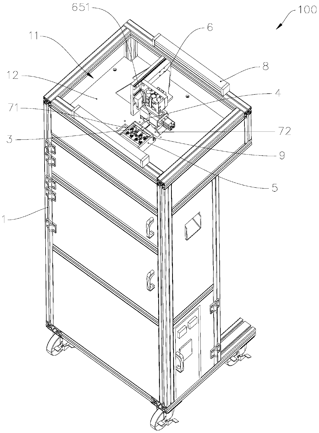
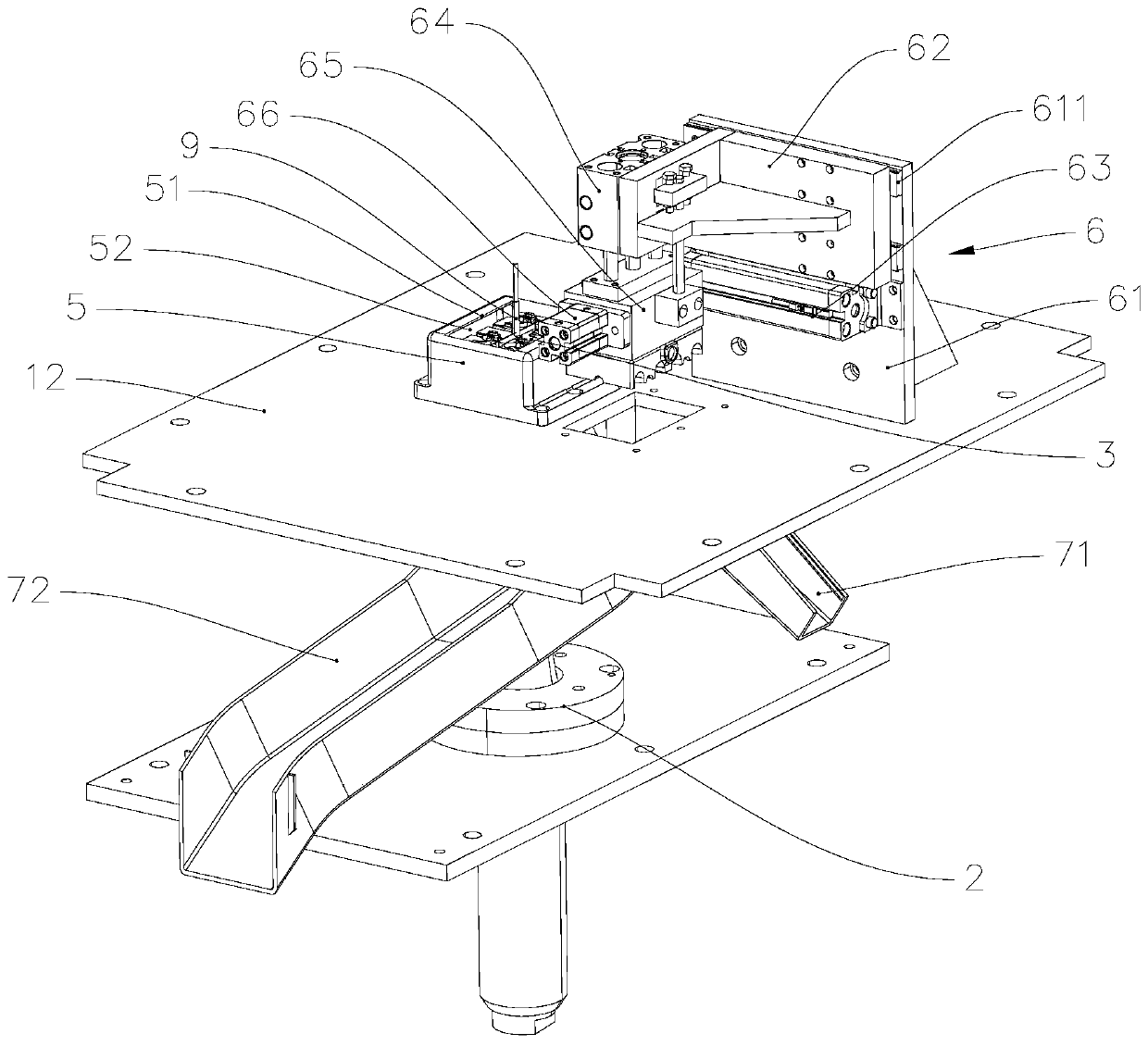
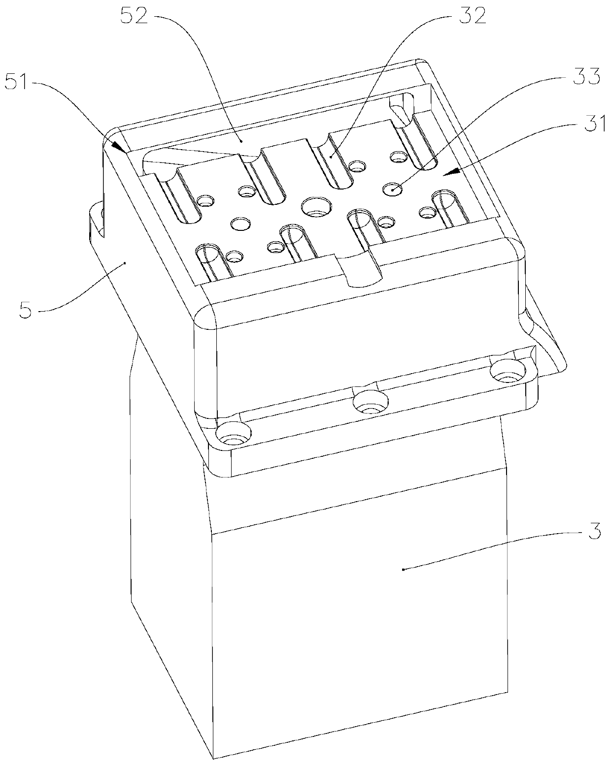
[0041] refer to figure 1 and figure 2 , The ultrasonic water outlet machine 100 includes a frame 1, an ultrasonic vibrator 2, a vibration seat 3, a cooling mask 4, a diversion shell 5, a driving device 6, a second slide 71, a third slide 72 and a safety grating 8.

[0042] Among them, the frame 1 has a processing chamber 11, the vibrating seat 3, the cooling mask 4, the diversion shell 5 and the driving device 6 are all arranged in the processing chamber 11, and the safety grating 8 is arranged at the mouth of the processing chamber 11. The safety grating 8 is used for real-time signal feedback to the control system connected with it, so that when a foreign object penetrates into the processing chamber 11 during the ultrasonic water removal machine 100 processing the workpiece 9, the safety grating 8 can be in time. Send a feedback signal to the control system connected with it, so that the control system controls the ultrasonic water outlet machine 100 to suspend operation,...


PUM


Abstract

The invention provides an ultrasonic water gate removing machine. The ultrasonic water gate removing machine comprises a rack, an ultrasonic vibrator, a vibrating base, a cooling face cover and a driving device. The ultrasonic vibrator is fixedly mounted on the rack. The vibrating base is fixedly mounted on the ultrasonic vibrator. The top of the vibrating base is provided with a carrying position. The carrying position is provided with discharge grooves. The top of the vibrating base is separably covered with the cooling face cover. The cooling face cover is provided with an air inlet hole, air outlet holes and an air flow channel. The air flow channel communicates with the air inlet hole and the air outlet holes. The air outlet holes face the discharge grooves. The driving device is mounted on the rack. The execution end of the driving device is fixedly connected with the cooling face cover. The driving device can drive the cooling face cover to move relative to the vibrating base. The ultrasonic water gate removing machine has the advantages of being suitable for cutting thick water gates and capable of avoiding secondary fusion welding, flanging or wire drawing in the cutting process.

Description

technical field [0001] The invention relates to the technical field of water outlet equipment, in particular to an ultrasonic water outlet machine. Background technique [0002] Injection molding is often used to shape products with complex structures, and the products formed by injection molding will be consolidated on the nozzle, so the product needs to be treated to remove the nozzle to separate the product from the nozzle. The existing nozzle removal methods mainly use cutting tools such as cutters, scissors, and lasers to cut the nozzle, but the disadvantages of the above removal methods are: whitening and irregular fractures are prone to occur when the fracture is cold cut. Problems such as flanging, wire drawing, inaccurate fracture size and excessive residue are prone to occur during eager cutting. [0003] In addition, ultrasonic sprue removal machines have begun to appear on the market at present, but the existing ultrasonic spout removal machines have the disadva...

Claims


Application Information

Patent Timeline
Patent Type & Authority Applications(China)
IPC IPC(8): B29C45/38B29C45/84
CPCB29C45/382B29C45/84
Inventor 李石桥苏信雅莫松德钱彬
Owner SUNWAY PLASTIC INJECTION MOLD ZHUHAI
Why Eureka
Try Eureka