Low floor rail flat car, bogie and welding method

A bogie and low-floor technology, applied in bogies, welding equipment, transportation and packaging, etc., can solve the problems of inability to meet the requirements of subway flat cars, large longitudinal positioning rigidity of wheels, and inability to meet subway flat cars, etc. Light weight, reduced installation height, and small structure size

Active Publication Date: 2019-11-08
ZHUZHOU XUYANG ELECTRICAL & MECHANICAL TECH DEV CO LTD
View PDF7 Cites 0 Cited by
  • Summary
  • Abstract
  • Description
  • Claims
  • Application Information

AI Technical Summary

Problems solved by technology

[0003] However, the height of the upper surface of the wear plate of the lower center plate of the domestically designed three-piece cast steel bogie from the rail surface (empty car state) is greater than 670mm, which cannot meet the requirements of flat cars for subways.
The welded frame bogie is an overall structure in which the side frame and the center beam are welded into an H shape. The cross section of the center beam at the center plate is higher, resulting in a higher overall bearing surface, which cannot meet the requirements of the subway flat car.
[0004] After searching, it was found: the patent publication number is CN102050135A, and the publication date is 2011.05.11. The Chinese invention patent discloses a new type of welded frame bogie, including wheel sets and frames. For axles and wheels, the frame is an H-shaped welded one-piece rigid frame, which can meet the requirement that the upper plane of the wear plate of the bogie lower center plate is no more than 550mm from the rail surface (in the empty state), but the welded frame bogie has a wheel The rigidity of the longitudinal positioning makes it relatively difficult to pass through the curve, uneven braking force transmission, serious wear of the wheels and rims, etc., which brings many problems to production, operation and maintenance.

Method used


Image

  • Low floor rail flat car, bogie and welding method
  • Low floor rail flat car, bogie and welding method
  • Low floor rail flat car, bogie and welding method

Examples


Embodiment

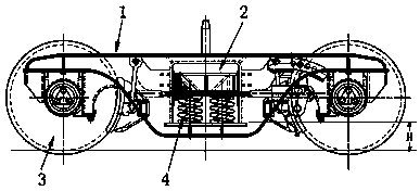
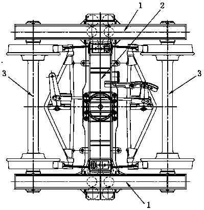
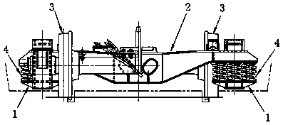
[0039] Example: such as Figures 1 to 3 As shown, a three-piece bogie with a low load-bearing surface welded type includes: two side frames 1 and a bolster 2 assembled, and also includes: two sets of wheels 3 and springs 4; the wheels 3. It consists of an axle, two wheels and two sets of bearings. The bearings are set on both ends of the axle, and the wheels are set on the bearings; The card frame 14 of the wheel set is installed, and the position of the central symmetrical axis of the side frame 1 is provided with an axle box 15; The side bearing box 26 is provided at the position close to the bolster neck 29; the wheel set 3 is stuck in the frame 14 at both ends of the side frame 1, and the bolster necks 29 at the two ends of the bolster 2 are respectively stuck in the In the axle boxes 15 of the two side frames, a spring 4 is vertically installed at the bottom of the axle boxes 15 to support the bolster 2; The parts are all formed by welding steel plates.

[0040] This w...


PUM

PropertyMeasurementUnit
diameteraaaaaaaaaa

Abstract

The invention also relates to a low floor rail flat car bogie comprising two sets of wheel pairs, springs and three main parts formed by two side frames and a swing bolster. The side faces of the sideframes are provided with saddle-shaped large circuitous arc shapes, the height of a bottom plate of a shaft box is reduced, the height of the portion, where a lower core disc is fixed, of the middleportion of the swing bolster is lower than the height of the two ends, and the height of the bearing surface of the bogie is further reduced. After the technical measures are taken, the height difference between the surface of the lower core disc and the rail surface is not larger than 495 mm, and the requirement for the low bearing surface of a subway flat car is met. The invention also relates to the low floor rail flat car comprising the bogie and a car body mounted on the bogie; and when the low floor rail flat car is no-load, the height of a floor from the rail surface is not higher than800 mm, loading, unloading and transportation of engineering equipment and apparatuses are facilitated, and meanwhile, the net height and the effective volume on the floor are increased.

Description

technical field [0001] The invention relates to a rail vehicle and a bogie, in particular to a low-floor rail flat car, a bogie and a welding method. Background technique [0002] In the subway construction, a special engineering flat car is required. Since the floor surface of the special engineering flat car required by the subway construction is not higher than the rail surface (empty car) is not more than 900mm, the distance between the upper plane of the wear plate of the bogie lower center disc and the rail surface is less than 900mm. The height (empty car state) is not more than 550mm. [0003] However, the height of the upper surface of the wear plate of the lower center plate of the domestically designed three-piece cast steel bogie from the rail surface (empty car state) is greater than 670 mm, which cannot meet the requirements of flat cars for subways. The welded frame bogie is an overall structure in which the side frame and the center sill are welded into an H...

Claims


Application Information

Patent Timeline
Patent Type & Authority Applications(China)
IPC IPC(8): B61F5/52B23K31/02
CPCB23K31/02B61F5/52
Inventor 邓建华叶备杨永州匡汝佳
Owner ZHUZHOU XUYANG ELECTRICAL & MECHANICAL TECH DEV CO LTD
Why Eureka
Try Eureka